http://safety.fhwa.dot.gov
FHWA Safety Program
Methods and Practices for
Setting Speed Limits:
An Informational Report
FHWA-SA-12-004
Institute of
Transportation Engineers

Disclaimer
The contents of this handbook reflect the views of the authors, who are responsible for the facts and the
accuracy of the data published herein. The contents do not necessarily reflect the official view or policies of
the Federal Highway Administration (FHWA). This handbook does not constitute a standard, specification, or
regulation. It is not intended for construction, bidding, or permit purposes.
Notice
The United States Government does not endorse products or manufacturers. Trade or manufacturers’
names appear herein solely because they are considered essential to the object of this handbook.
Acknowledgments
Gerald J. Forbes (F) served as the ITE Project Consultant and the overall technical editor for this report. He was
responsible for the technical content and developing the case studies.
This report was based on a draft report, Best Practices for Setting Rational Speed Limits, prepared by Vanasse Hangen
Brustlin, Inc. for the Federal Highway Administration, Office of Safety in May, 2009. Westat and Raghavan Srinivasan
assisted in the development of the FHWA draft report.
ITE would like to acknowledge the following individuals who supplied information or provided comments in the
development of this informational report:
Tony S. Abbo (M)
Richard F. Beaubien (F)
Leanna M. Belluz (M)
Robert Bucholc
Harry A. Campbell (F)
Tom Carmody
Christopher J. Dack (F)
Chris C. Day (M)
Andrew W. Edgar (M)
James W. Ellison (F)
John E. Fisher (F)
Kay Fitzpatrick (F)
Jenny L. Grote (F)
Abdullah J. Habibzai
Lawrence T. Hagen (F)
Wen Hu (M)
Kenton R. Jones
Arash Khoshghalb (M)
Chris King
Ryan C. Kump (M)
Greg M. Laragan (F)
Matthew P. Lawrie (M)
Mark A. Madden (M)
Sean P. Merrell (M)
Rock E. Miller (F)
Craig S. Neustaedter (F)
Michael D. Nichols (M)
Kwabena Ofosu (M)
Martin R. Parker Jr. (M)
Veronica Pelkey
Eduardo A. Petil (M)
William B. Raffensperger (M)
Lawrence E. Sefcik
Douglas A. Skowronek (M)
Harry W. Thompson (F)
Blair Turner
Elia Twigg
David C. Woodin (F)
Peter J. Yauch (F)
Erik H. Zandvliet (M)
ITE would like to acknowledge the ITE Traffic Engineering Council technical committee members who reviewed and
provided comments on this report:
Gerald J. Forbes (F), Chair
Geni B. Bahar (M)
Marcus A. Brewer (M)
Wen Cheng (M)
John A. Davis (F)
Melisa D. Finley (M)
Paul Mackey (M)
Richard J. Porter (M)
Keith B. Rohling (M)
Kelly I. Schmid (M)
Rick J. Staigle (M)
James E. Tobaben (F)
John W. Van Winkle (M)
ITE would also like to acknowledge the Federal Highway Administration staff that reviewed and provided comments on
this report:
Guan Xu (M), FHWA Project Manager
Craig Allred
James E. (Eric) Ferron (M)
Michael S. Griffith (M)
Note: Letters in parentheses indicate ITE member grade: M—Member, F—Fellow.

SI* (Modern Metric) Conversion Factors
Approximate Conversions to SI Units
Symbol When You Know Multiply By To Find Symbol
Length
in inches 25.4 millimeters mm
ft feet 0.305 meters m
yd yards 0.914 meters m
mi miles 1.61 kilometers km
Area
in
2
square inches 645.2 square millimeters mm
2
ft
2
square feet 0.093 square meters m
2
yd
2
square yard 0.836 square meters m
2
ac acres 0.405 hectares ha
mi
2
square miles 2.59 square kilometers km
2
Volume
fl oz fluid ounces 29.57 milliliters mL
gal gallons 3.785 liters L
ft
3
cubic feet 0.028 cubic meters m
3
yd
3
cubic yards 0.765 cubic meters m
3
NOTE: volumes greater than 1000 L shall be shown in m
3
Mass
oz ounces 28.35 grams g
lb pounds 0.454 kilograms kg
T short tons (2000 lb) 0.907 megagrams (or “metric ton”) Mg (or “t”)
Temperature (exact degrees)
o
F Fahrenheit 5 (F-32)/9 or (F-32)/1.8 Celsius
o
C
Illumination
fc foot-candles 10.76 lux lx
fl foot-Lamberts 3.426 candela/m
2
cd/m
2
Force and Pressure or Stress
lbf pound force 4.45 Newtons N
lbf/in
2
pound force per square inch 6.89 kilopascals kPa
* SI is the symbol for the International System of Units. Appropriate rounding should be made to comply with Section 4
of ASTM E380.
(Revised March 2003)
iv

Approximate Conversions from SI Units
Symbol When You Know Multiply By To Find Symbol
Length
mm millimeters 0.039 inches in
m meters 3.28 feet ft
m meters 1.09 yards yd
km kilometers 0.621 miles mi
Area
mm
2
square millimeters 0.0016 square inches in
2
m
2
square meters 10.764 square feet ft
2
m
2
square meters 1.195 square yards yd
2
ha hectares 2.47 acres ac
km
2
square kilometers 0.386 square miles mi
2
Volume
mL milliliters 0.034 fluid ounces fl oz
L liters 0.264 gallons gal
m
3
cubic meters 35.314 cubic feet ft
3
m
3
cubic meters 1.307 cubic yards yd
3
Mass
g grams 0.035 ounces oz
kg kilograms 2.202 pounds lb
Mg (or
“t”)
megagrams (or “metric
ton”)
1.103 short tons (2000 lb) T
Temperature (exact degrees)
o
C Celsius 1.8C+32 Fahrenheit
o
F
Illumination
lx lux 0.0929 foot-candles fc
cd/m
2
candela/m
2
0.2919 foot-Lamberts fl
Force and Pressure or Stress
N Newtons 0.225 pound force lbf
kPa kilopascals 0.145 pound force per square inch lbf/in
2
* SI is the symbol for the International System of Units. Appropriate rounding should be made to comply with Section 4
of ASTM E380.
(Revised March 2003)
v
TABLE OF CONTENTS
BACKGROUND ........................................................................................................................... 1
PURPOSE AND SCOPE ................................................................................................................ 2
REPORT ORGANIZATION ............................................................................................................ 3
THE SAFETY OF SPEED ................................................................................................................. 4
SPEED LIMIT BASICS .................................................................................................................... 6
Types of Speed Limits ................................................................................................................................. 6
Statutory Speed Limits ........................................................................................................................... 6
Speed Zones .......................................................................................................................................... 8
SETTING SPEED LIMITS ................................................................................................................. 9
Methods of Setting Speed Limits ............................................................................................................ 10
Engineering Approach ....................................................................................................................... 11
Operating Speed Method ............................................................................................................ 12
Road Risk Method .......................................................................................................................... 15
Expert System—USLIMITS2 ................................................................................................................... 16
Overview of the Decision Rules and Data Requirements of USLIMITS2 .................................... 17
Optimal Speeds ................................................................................................................................... 21
Injury Minimization ............................................................................................................................... 22
Minimum Length of Speed Zones ........................................................................................................... 25
Special Situations ..................................................................................................................................... 27
Advisory Speeds .................................................................................................................................. 27
Nighttime Speed Limits ....................................................................................................................... 28
School Zone Speed Limits ................................................................................................................... 28
Work Zone Regulatory Speeds ........................................................................................................... 30
Truck Speed Limits ............................................................................................................................... 30
Minimum Speed Limits ........................................................................................................................ 30
Variable Speed Limits .......................................................................................................................... 30
Transition Zone Speed Limits ............................................................................................................... 31
Seasonal or Holiday Speed Limits ...................................................................................................... 31
Reevaluation ............................................................................................................................................ 32
SPEED LIMIT SIGN DESIGN AND PLACEMENT .......................................................................... 33
Speed Feedback Signs ............................................................................................................................ 35
SPEED STUDY DATA COLLECTION ............................................................................................. 37
Data Collection Planning and Coordination ....................................................................................... 37
vi
Study Area ................................................................................................................................................ 39
Speed Data Collection ........................................................................................................................... 42
Vehicle Speeds .................................................................................................................................... 42
Speed Test Runs ................................................................................................................................... 48
Data Analysis ............................................................................................................................................ 49
85th Percentile Speed ........................................................................................................................ 49
10 mph (16 km/h) Pace ...................................................................................................................... 50
Crash Data ........................................................................................................................................... 50
SPEED LIMIT ENFORCEMENT ..................................................................................................... 52
CASE STUDIES ............................................................................................................................ 53
CASE STUDY 1: Urban Collector Road ................................................................................................... 54
Engineering Method Using Operating Speed ...................................................................................... 55
Using the Illinois DOT Method ............................................................................................................. 55
Using the Northwestern Speed Zoning Technique .......................................................................... 57
Expert Systems Approach Using USLIMITS2 ............................................................................................ 58
Optimal Speed Limit ........................................................................................................................... 60
Safe Systems Approach ..................................................................................................................... 64
CASE STUDY 2: Rural Arterial Road ......................................................................................................... 65
Engineering Method Using Operating Speed ...................................................................................... 67
Using the Illinois DOT Method ............................................................................................................. 67
Using the Northwestern Speed Zoning Technique .......................................................................... 69
Expert System (USLIMITS2) ........................................................................................................................ 71
Optimal Speed Limit ................................................................................................................................ 71
Safe Systems Approach .......................................................................................................................... 74
SUMMARY OF RESULTS .............................................................................................................. 75
REFERENCES .............................................................................................................................. 76
APPENDIX A: GLOSSARY .......................................................................................................... 79
APPENDIX B: EXAMPLE TRAFFIC CONTROL ORDER ................................................................ 81
APPENDIX C: ILLINOIS POLICY ON SETTING SPEED LIMITS ..................................................... 82
APPENDIX D: NORTHWESTERN SPEED ZONING TECHNIQUE ................................................... 84
APPENDIX E: SPEED LIMITS NEW ZEALAND (ROAD RISK METHODOLOGY) ............................ 92
APPENDIX F: EXAMPLE CASE STUDY USING USLIMITS2 ........................................................... 99
APPENDIX G: EXAMPLE SPEED STUDY FORMS ....................................................................... 104
APPENDIX H: SAMPLE 85th PERCENTILE SPEED CALCULATION ............................................ 106
vii
TABLES
Table 1. Examples of Speed Limit Statutes .............................................................................................. 7
Table 2. Base Speed for the Classification and Land Use Combination ........................................... 15
Table 3. USLIMITS2 Data Inputs for Road Types ..................................................................................... 18
Table 4. Speed Limits for Injury Minimization.......................................................................................... 23
Table 5. Approaches to Setting Speed Limits ....................................................................................... 24
Table 6. Minimum Lengths of Speed Zones in New Zealand .............................................................. 26
Table 7. Minimum Length of Road for a Speed Limit ........................................................................... 27
Table 8. Maximum Speeds to Trigger a Speed Feedback Sign .......................................................... 36
Table 9. Information to Show on Strip Map ........................................................................................... 41
Table 10. Advantages and Disadvantages of Speed Collection Devices ....................................... 43
Table 11. Example Calculation of Sample Size for Study to Determine 85th Percentile Speed ..... 44
Table 12. Sample Sizes and Data Collection Periods Used by Three States ...................................... 45
Table 13. Speed Check Stations for Three States ................................................................................. 47
Table 14. Example of Using Speed Test Runs to Confirm 85th Percentile Speeds ............................. 49
Table 15. Recommended Speed Limits for the Eldron Boulevard Case Study ................................. 64
Table 16. Recommended Speed Limits for the State Route 67 Case Study ..................................... 74
Table 17. Recommended Speed Limits for the Case Studies ............................................................. 75
Table 18. Speed Limit Justified by Speed Data..................................................................................... 85
Table 19. Speed Limit Based on Road Parameters .............................................................................. 86
Table 20. Adjustment Factors for Access Density ................................................................................. 87
Table 21. Adjustment Factors for Lane Width ....................................................................................... 87
Table 22. Adjustment Factors for Functional Classification ................................................................. 87
Table 23. Adjustment Factors for Median Type .................................................................................... 88
Table 24. Adjustment Factors for Shoulder Type and Width ............................................................... 88
Table 25. Adjustment Factors for Pedestrian Activity ........................................................................... 88
Table 26. Adjustment Factors for Parking Activity ................................................................................ 89
Table 27. Adjustment Factors for Roadway Alignment ....................................................................... 89
Table 28. Adjustment Factors for Crash Rate ........................................................................................ 89
Table E1. Development Rating ............................................................................................................... 93
Table E2. Side Road Development Rating ............................................................................................ 94
Table E3. Pedestrians ............................................................................................................................... 95
Table E4. Cyclists ....................................................................................................................................... 95
Table E5. Parking ...................................................................................................................................... 95
Table E6. Road Geometry ....................................................................................................................... 96
Table E7. Traffic Control ........................................................................................................................... 96
Table E8. Development ........................................................................................................................... 96
Table 29. Example Frequency Distribution Table ................................................................................ 106
viii

FIGURES
Figure 1. Speed Limit Study Process for Engineering and Expert Systems Methods ......................... 11
Figure 2. Optimal Speed Limit Process. .................................................................................................. 22
Figure 3. International Speed Limit Signs ............................................................................................... 33
Figure 4. Example Regulatory Speed Zone Application Showing Spacing of
Signs Transitioning from Rural District to Urban District and Within the Urban District. ...... 34
Figure 5. Speed Feedback Sign ............................................................................................................. 35
Figure 6. An Example of a Strip Map of a Study Area Showing Existing Conditions ......................... 40
Figure 7. Radar Setup .............................................................................................................................. 46
Figure 8. Portable Traffic Analyzer .......................................................................................................... 46
Figure SLNZ1. Determining Speed Limit. ................................................................................................. 97
Figure SLNZ2. Speed Limit Flow Chart—Rural. ....................................................................................... 97
Figure SLNZ3. Speed Limit Flow Chart—In-Between. ............................................................................ 98
Figure SLNZ4. Speed Limit Flow Chart—Urban. ..................................................................................... 98
ix

1
BACKGROUND
In 1885, Karl Friedrich Benz revealed the first gasoline-powered automobile on the public street
system.
1
The fastest his car could go was about 13 mph (21 km/h). Since that time, advances in
science and technology have brought faster vehicles and better roads, both of which have served
to increase travel speeds for automotive travel. Today, attainable speeds are far higher than the
maximum speeds that society generally accepts as reasonable for motorized travel on public streets,
yet the speedometers on most motor vehicles display maximum speeds that far exceed the maximum
legal speed limits on most roads.
Speeding, commonly defined as exceeding the posted speed limit or driving too fast for conditions,
is a primary crash causation factor across the globe. Based on a survey of road safety performance,
speeding is the number one road safety problem in many countries, often contributing to as many
as one-third of fatal crashes and serving as an aggravating factor in most crashes.
2
According to the
National Highway Traffic Safety Administration (NHTSA), speeding-related crashes account for over
13,000 fatalities per year in the United States, making speeding one of the most often-cited contributing
factors for fatal crashes.
3
One of the most frequently used methods of managing travel speeds is the posted speed limit. The setting
of speed limits predates the automobile by some 200 years, when Newport, Rhode Island, prohibited the
horses galloping on major thoroughfares to prevent pedestrian deaths. Similarly, Boston, Massachusetts,
limited horse-drawn carriages to “foot pace” on Sundays to protect church-goers.
The English Parliament is credited with setting the world’s first speed limit for mechanically-propelled
vehicles in 1861.
*
At that time, the Locomotive Act (automobiles were considered “light locomotives”)
limited the speed of all “locomotives” on public highways to 10 mph (16 km/h)–5 mph (8 km/h) through
any City, town, or village.
4
The Act was later amended to set speed limits of 4 mph (6 km/h) outside of
towns and 2 mph (3 km/h) within them. These new operating speeds also required three operators for
each vehicle—two traveling in the vehicle and one walking ahead and carrying a red flag to warn
pedestrians and equestrians.
5
Selecting an appropriate speed limit for a facility can be a polarizing issue for a community. Residents
and vulnerable road users generally seek lower speeds to promote quality of life for the community and
increased security for pedestrians and cyclists; motorists seek higher speeds that minimize travel time.
Despite the controversy surrounding maximum speed limits, it is clear that the overall goal of setting the
speed limit is almost always to increase safety within the context of retaining reasonable mobility.
The principal exception to the safety objective of speed limits was the oil crisis in the early 1970s, when
speed limits were lowered as a means of conserving fuel. This rationale for lower speed limits was revived
in Spain in early 2011, where the government lowered the maximum speed limit of 75 mph (120 km/h)
to 70 mph (110 km/h) in an attempt to curb fuel consumption in the face of rising oil prices.
6
However,
the measure lasted only four months before the top speed limit was returned to the former 75 mph (120
km/h).
Maximum speed limits are laws; therefore, speed limits are set for the protection of the public and the
regulation of unreasonable behavior on the part of individuals.
*
This still predates the gasoline-powered automobile and was enacted for steam-powered vehicles.

2
PURPOSE AND SCOPE
Despite the wide-spread acceptance and use of speed limits throughout the world, there has been no
consensus among practitioners concerning the methods and techniques that should be used to select
the most appropriate speed limit for a particular facility. Currently, it appears unlikely that consensus will
be achieved in the near future. This leaves practitioners without definitive guidance on this important
issue, and in search of information that may assist them. This report provides the information necessary
for practitioners to make informed decisions concerning the method that is selected for setting speed
limits in their jurisdiction.
This report presents the various procedures that highway agencies can and do use to set speed limits.
It is an informational report and provides a broad overview of the different speed limit setting methods
that are available, but makes no specific recommendations or suggestions.
Special situations, such as advisory, school zone, and work zone speeds are discussed. Speed limit
enforcement and periodic reevaluation of speed limits are discussed briefly. The design speed for
the roadway will not be discussed, except as it relates to the setting of speed limits. This is because
design speed is a characteristic of the roadway that is essentially “built-in” to the road, and is not easily
modified.
Technical terms are defined in Appendix A.

3
REPORT ORGANIZATION
The remainder of this report is organized into eight sections as follows:
THE SAFETY OF SPEED: As speed limits are first and foremost a road safety measure, a discussion on the
effects of speed on crash risk is provided for the information of the user.
SPEED LIMIT BASICS: An introduction to the broad categories and types of speed limits, including
statutory speed limits, prima facie speed limits, and speed zoning.
SETTING SPEED LIMITS: A detailed description of the various methods that are available for setting speed
limits, a brief discussion of special types of speed limits (i.e., nighttime speed limits, school zone speed
limits, truck speed limits, etc.), and information on minimum lengths of speed zones.
SPEED LIMIT SIGN DESIGN AND PLACEMENT: Criteria that are used in selecting sign types and in the
placement of the signs for speed zones and speed transitions. Also included is some information on
Speed Feedback signs.
SPEED STUDY DATA COLLECTION: An outline of the data required for determining a posted speed limit
with emphasis on spot speed data collection and analysis.
SPEED LIMIT ENFORCEMENT: A brief discussion on the role of engineering practitioners in assisting with the
enforcement of speed limits.
CASE STUDIES: Two case studies that demonstrate the use of several available methods for setting
speed limits.
REFERENCES AND APPENDICES: Supporting information and additional details for the reader.

4
THE SAFETY OF SPEED
It is important to understand how speed impacts safety, because setting speed limits is primarily a
road safety measure. While the laws of physics make it very clear that speed and crash severity are
inextricably linked (i.e., severity increases geometrically as speed increases), there has been a good
deal of controversy over the impact of speed on crash occurrence. This is primarily because the variety
of road design and operating characteristics can obscure the precise relationship between speed and
crash occurence. Numerous studies and research efforts on this topic that have presented conflicting
results on this important relationship. However, the most recent and statistically robust research on speed
and crash occurrence fairly definitively indicates that, all other factors being equal, increased speeds
increase crash occurrence.
7
The magnitude of the increase is dependent on the specifics of each case,
with urban areas having the most pronounced relationship and controlled-access facilities the weakest.
One of the most statistically robust efforts to uncover the relationship between speed and safety was
a meta-analysis conducted by the Norwegian Institute of Transport Economics.
7
The information and
conclusions from the meta-analysis form the basis for the statements made in this section.
For a given roadway type, there is a strong statistical relationship between speed and crash risk for
speeds in the range of 15 mph to 75 mph (25 km/h to 120 km/h). When the mean speed of traffic is
reduced, the number of crashes and the severity of injuries will almost always go down. When the
mean speed of traffic increases, the number of crashes and the severity of injuries will usually increase.
The relationship between mean travel speed and crash risk can be adequately described in terms of
the following model:
x
b
a
V
V
CMF
⎟
⎟
⎠
⎞
⎜
⎜
⎝
⎛
=
CMF = Crash modification factor
V
a
= Mean speed in the after condition
V
b
= Mean speed in the before condition
X = 3.6 for fatal crash frequency
2.0 for injury crash frequency
1.0 for property-damage-only crash frequency
4.5 for fatalities
2.7 for personal injuries
The relationship between speed and crash risk can be modified to some extent by road environment,
vehicle-related factors, and driver behavior. But, the effects of speed on crash risk are remarkably
consistent across different contexts.
The above relationship between speed and crash risk is significantly different from the traditional
U-shaped relationship that has defined much of the current North American thinking on speed limits
and speed management. The U-shaped relationship (Solomon curve) between speed and crash risk
can be questioned for two reasons:

5
1. The U-shape is generally expected to be an artifact of errors in the measurement of speed
8,9
; and
2. There is a strong correlation between mean speed and speed variance, so it is difficult to separate
the effects of mean speed and speed variance on crash risk.
10
This discussion describes the relationship between travel speed and crash risk, but it does not necessarily
reflect the relationship between speed limits and crash risk.
A change in the speed limit almost always changes the mean speed of traffic. However, the changes
are not always proportional. For the most part, the change in the mean speed of traffic created by a
change in speed limit is around 25 percent of the change in the speed limit.
7
In other words, a speed
limit increase or reduction of 6 mph (10 km/h) yields about a 1.5 mph (2.5 km/h) raising or lowering of
the mean speed, respectively. When this statistic is combined with the power formula equating change
in mean speed to crash risk, it is evident that lowering the speed limit will reduce crash risk, and raising
the speed limit will increase crash risk.
Whether the safety gains/losses associated with the change in the speed limit is worthwhile must be
examined in the context of maintaining reasonable mobility, and other system objectives. In addition,
the policy context must be considered because the relationship between travel speed and speed
limits indicates that the percentage of violators increases when speed limits are lowered and decreases
when speed limits are increased.

6
SPEED LIMIT BASICS
Setting speed limits in the United States has always
been a responsibility of State and local governments.
The unrestricted freedom to exercise that authority was
interrupted by the Federal Government during World War
II, and more recently with the National Maximum Speed
Limit of 55 mph (90 km/h). The National Maximum Speed
Limit was repealed in 1995.
Every State has a basic speed statute requiring drivers to
operate their vehicles at a speed that is reasonable and
prudent for conditions. This basic rule is contained in the
Uniform Vehicle Code (UVC), which provides a model set
of motor vehicle laws to encourage uniformity in State
traffic regulation. State statutes authorize maximum speed
limits that may vary by highway type (e.g., interstate
highways) or location (e.g., urban district).
11
The UVC is a set of model traffic laws that was originally
developed by the National Committee on Uniform Traffic
Laws and Ordinances (NCUTLO), a now defunct, private,
non-profit organization. The NCUTLO’s members were
mainly State governments and some related organizations.
The extent to which the code is used varies by State. The
UVC and most State motor vehicle laws include a basic
speed law with wording similar to the following: No person
shall drive a vehicle at a speed greater than is reasonable
and prudent under the conditions and having regard for
the weather, visibility, traffic, and the surface and width of
the roadway.
11
Section 11-803 of the UVC recommends States establish speed zones upon the basis of an engineering
and traffic investigation. Section 11-804 outlines recommended practices on how local authorities may
alter maximum limits.
12
Types of Speed Limits
Speed limits may be classified as default/statutory regulations, or speed zoning regulations established
on the basis of engineering studies. In all cases, a speed limit must be legislated (i.e., established by
legislative authority).
Statutory Speed Limits
Statutory limits are based on the concept that uniform categories of highways can operate safely
at certain maximum speeds under ideal conditions. State motor vehicle laws specify speed limits on
specific categories of streets and highways. For example, a vehicle code might limit speeds to 25 mph
(40 km/h) in residential areas, 30 mph (50 km/h) in business districts, and 55 mph (90 km/h) on all other
roads. Generally, statutory limits apply throughout a political jurisdiction.
11
Table 1 contains examples of
statutory limits for three States and for the Uniform Vehicle Code.
Article VIII—Speed Restrictions
11-801—Basic rule
No person shall drive a vehicle at a
speed greater than is reasonable
and prudent under the conditions
and having regard to the actual
and potential hazards then existing.
Consistent with the foregoing, every
person shall drive at a safe and
appropriate speed when approaching
and crossing an intersection or railroad
grade crossing, when approaching
and going around a curve, when
approaching a hill crest, when
traveling upon any narrow or winding
roadway, and when special hazards
exist with respect to pedestrians or
other traffic or by reason of weather or
highway conditions. (Revised, 1968)
Uniform Vehicle Code and Model Traffic
Ordinance, 2000, National Committee
on Uniform Traffic Laws and Ordinances,
Evanston, Illinois.

7
Table 1. Examples of Speed Limit Statutes
Jurisdiction Speed Limit Statute
Uniform Vehicle Code 55 mph (90 km/h) in locations other than urban districts
35 mph (60 km/h) in urban districts
Delaware Where no special hazard exists, the following speeds shall be lawful, but any
speed in excess of such limits shall be absolute evidence that the speed is not
reasonable or prudent and that it is unlawful:
All types of vehicles:
25 mph (40 km/h) in any business district
25 mph (40 km/h) in any residential district
20 mph (30 km/h) at all school zones where 20 mph (30 km/h) regulatory signs
are in effect during specific periods
50 mph (80 km/h) on 2-lane roadways
55 mph (90 km/h) on 4-lane roadways and on divided roadways
Minnesota 10 mph (15 km/h) in alleys
30 mph (50 km/h) on streets in urban districts
70 mph (110 km/h) on rural interstate highways
65 mph (105 km/h) on urban interstate highways
65 mph (105 km/h) on expressways
55 mph (90 km/h) on other roads
Oregon 15 mph (25 km/h) – alleys; narrow residential roadways
20 mph (30 km/h) – business districts, school zones
25 mph (40 km/h) – residential districts, public parks, ocean shores
55 mph (90 km/h) – open rural highways, trucks on interstate highways
65 mph (105 km/h) – passenger vehicles, light trucks, motor homes, and light
duty commercial vehicles on interstate highways.
Statutory speed limits allow for speed limits to be in effect even when it is not practical to post them.
There are two types of statutory speed limits: (a) absolute limits and (b) prima facie limits. The principle
difference between the two types is whether someone who is charged with driving over the speed
limit can defend her/his actions. An absolute speed limit is a limit above which it is unlawful to drive
regardless of roadway conditions, the amount of traffic, or other influencing factors. There is no recourse
to contend a charge. A prima facie speed limit is one above which drivers are presumed to be driving
unlawfully but, if charged with a violation, they may contend that their speed was safe for conditions
existing on the roadway at that time. And, therefore, that they are not guilty of a speed limit violation.
Prima facie limits provide greater flexibility to drivers to determine an appropriate speed for conditions
and place a greater burden of proof on the enforcement community that a violation has occurred.

8
Approximately two-thirds of the States have absolute speed limits.
11
Speed Zones
Where statutory limits do not fit specific road, traffic, or land uses conditions, most road authorities
have the power to establish speed zones to reflect the safe maximum reasonable speed. These
alternative speed limits may be higher or lower than those prescribed by the UVC or the statutory
limits of the jurisdiction. Alternative maximum legal speed limits are established by legislating the
speed zone, typically founded on the basis of an engineering study, and becoming effective when
the limits are posted and properly recorded.
11
Agencies process resolutions, traffic control orders,
or other formal documents to properly record the legal speed limit. An example of a Traffic Control
Order is shown in Appendix B.
To encourage compliance and effectively manage risk, many agencies set speed limits to reflect the
“reasonable and prudent” behavior of the majority of motorists acting in an appropriate manner. This
encourages drivers to obey the posted speed limit and travel at a reasonable speed. It also targets
limited enforcement resources at the occasional violator who disproportionately contributes to crash
risk. The concept of a rational speed limit involves a formal engineering review, during which drivers’
free-flowing speeds are observed. The assumption is that by reflecting actual driver speeds, most people
will consider the speed limit appropriate. Such speed limits are desirable because they encourage
public compliance, reduce speed differences among drivers, and offer a defensible enforcement tool.

9
SETTING SPEED LIMITS
This section describes the main objectives and guiding principles of setting speed limits and provides a
detailed description of the principal available methods.
Speed limits are set to inform motorists of appropriate driving speeds under favorable conditions.
Drivers are expected to reduce speeds under certain conditions (e.g., poor visibility, adverse weather,
congestion, warning signs, or presence of bicyclists and pedestrians). Legislation and statutes
generally reflect this requirement. All speed control regulations provide the legal basis for adjudication
and sanctions for violations of the law. Road authorities may also post advisory speed signs, which
do not have the force of law but warn motorists of suggested safe speeds for specific conditions at
a particular location (e.g., a turn or an intersection approach).
11
Having stated the above, however, a
motorist exceeding an advisory speed could still be cited under the basic speed rule (i.e., driving too
fast for the prevailing conditions).
The primary purpose of the speed limit is to advise drivers of the maximum reasonable and safe
operating speed under favorable conditions. It provides a basis for enforcement and ought to be fair in
the context of traffic law.
Methodologies for setting speed limits typically are designed to result in recommended speed limits that:
• Are related to crash risk;
• Provide a reasonable basis for enforcement;
• Are fair in the context of traffic law; and
• Are accepted as reasonable by a majority of road users.
The selected methodology is generally applicable on all road types and capable of being
implemented with existing resources.
Factors that affect safe speeds along roadways, and also influence the speed selected by motorists,
include:
• A vehicle’s mechanical condition and characteristics;
• Driving ability/capabilities;
• Traffic volume: vehicles, pedestrians, and bicycles;
• Weather and visibility;
• Roadway design elements, including:
» Road function/purpose;
» Lane and shoulder width;
» Horizontal and vertical curves;
» Available sight distances;
» Driveways with restricted visibility and other roadside developments;

10
» High driveway density;
» Rural residential or developed areas; and
» Paved or improved shoulders.
• Pavement conditions; and
• Crash frequency and severity.
All of these factors should be considered when designing appropriate speed limits at locations where
the speed limits need to be varied from the statutory limits. Special situations also exist that necessitate
nighttime, school zone, work zone, minimum and variable speed limits or advisory speeds.
The above-mentioned factors to be considered in selecting a speed limit are also heavily influenced
by geometric design features of the road and roadside development/activity. This is largely because
drivers tend to select operating speeds based on the visual scene presented to them. Therefore, the
speed limit and design of the road must work in concert if desired operating speeds are to be achieved.
Due to the lack of specific guidance and procedures from the Manual on Uniform Traffic Control
Devices (MUTCD) and other documents, engineers often rely on their experience and judgment when
considering factors that affect decisions about setting appropriate speed limits. The use of subjective
procedures by decision-makers with various levels of experience, and the use of different procedures
across jurisdictions, may lead to inconsistencies in how speed limits are set in different jurisdictions.
Methods of Setting Speed Limits
Within the traffic engineering community, there are four general approaches to setting speed limits:
• Engineering approach: A two-step process where a base speed limit is set according to the 85th
percentile speed, the design speed for the road, or other criterion. This base speed limit is adjusted
according to traffic and infrastructure conditions such as pedestrian use, median presence, etc.
Within the engineering approach there are two approaches; 1) Operating Speed Method and
2) Road Risk Method.
• Expert system approach: Speed limits are set by a computer program that uses knowledge and
inference procedures that simulate the judgment and behavior of speed limit experts. Typically,
this system contains a knowledge base containing accumulated knowledge and experience
(knowledge base), and a set of rules for applying the knowledge to each particular situation
(the inference procedure).
• Optimization: Setting speed limits to minimize the total societal costs of transport. Travel time,
vehicle operating costs, road crashes, traffic noise, and air pollution are considered in the
determination of optimal speed limits.
• Injury minimization or safe system approach: Speed limits are set according to the crash
types that are likely to occur, the impact forces that result, and the human body’s tolerance to
withstand these forces.
Engineering and expert system approaches are widely used in North America, injury minimization methods
are gaining wide-spread use in countries that are at the forefront of global road safety (i.e., Sweden,

11
Australia, etc.). The concept of setting optimal speed limits has been studied by some jurisdictions, but is
not known to have been adopted by any road authority. However, the optimal speed limits approach
seems applicable within the context of providing context sensitive solutions (CSS)—an approach that
considers the total context within which a facility will exist—and has been considered for application on
some New Jersey roads.
13
Speed limits set by either an engineering method or an expert system use similar basic tenets. The
engineering method is often limited to a basic study, while the expert system approach employs a
more structured set of decision and judgment rules. For both methods, the speed limit is determined by
considering the existing speed, roadway, and crash information. Figure 1 shows the steps that lead to
producing the final report for either an engineering or an expert systems type of speed study.
Speed limit studies are most often undertaken in response to a request for a lower speed limit
than currently posted. In some instances, however, the road authority finds itself in the position of
recommending a higher speed limit than the one currently posted. In these latter instances, some
jurisdictions require a road safety audit be conducted prior to a higher speed limit being approved.
14
The following sections detail the steps to setting speed limits using the four methods.
Engineering Approach
The steps in the engineering approach to setting speed limits include planning, coordination, data
collection and analysis, and finally, determination of the speed limits. A traffic engineering study is
the observation and analysis of road and traffic characteristics to guide the application of traffic
engineering principles. The study of speed limits includes the following:
Figure 1. Speed Limit Study Process for Engineering and Expert Systems Methods.
Select Study
Methodology
• Determine issue
at hand.
• Does the study
require a small or
large sample?
• Select the method
for collecting speed
data.
Select Location
• Select the proper
location.
• Plan the data
collection
preparations.
• Select a day
(Tuesday, Wednesday,
or Thursday).
• Complete
the pre-study
documentation.
Complete Study
• Collect the data.
• Evaluate the data.
• Calculate the speed
percentiles.
• Develop the limits of
the zone.
• Develop sign
locations.
Document
• Finalize the report.
• File the report.
• Communicate
the results.

12
• Review of the road’s environment, features, and condition and traffic characteristics.
• Observation and measurement of vehicle speeds at one or more representative spots along the
road in ideal weather and under free-flowing traffic conditions.
• Analysis of vehicle speeds to determine 85th percentile speed and other characteristics.
• Review of the road’s crash history.
• Review of any unusual conditions not readily apparent.
Setting speed limits is complex and often controversial. The engineering approach requires the use
of engineering judgment based on the engineering and traffic investigation. Quality data and good
documentation provides support for the judgments that are made.
Within the engineering approach to setting speed limits there are two basic methods: the operating
speed method and the road risk method. Each of these is detailed below.
Operating Speed Method
Most engineering approaches to speed limit setting are based on the 85th percentile speed—the speed
at which 85 percent of free-flowing traffic is traveling at or below. The typical procedure is to set the
speed limit at or near the 85th percentile speed of free-flow traffic. Adjustments to either increase or
decrease the speed limits may be made depending on infrastructure and traffic conditions.
Setting a speed limit based on the 85th percentile speed was originally based on safety. Specifically,
research at the time had shown that traveling at or around one standard deviation above the mean
operating speed (which is approximately the 85th percentile speed) yields the lowest crash risk for drivers.
Furthermore, crash risk increases rapidly for drivers traveling two standard deviations or more above or
below the mean operating speed. Therefore, the 85th percentile speed separates acceptable speed
behavior from unsafe speed behavior that disproportionately contributes to crash risk.
*
The 85th percentile speed method is also attractive because it reflects the collective judgment of
the vast majority of drivers as to a reasonable speed for given traffic and roadway conditions. This is
aligned with the general policy sentiment that laws (i.e., speed limits) should not make people acting
reasonably into law-breakers. Setting a speed limit even 5 mph (8 km/h) below the 85th percentile
speed can make almost half the drivers illegal; setting a speed limit 5 mph (8 km/h) above the 85th
percentile speed will likely make few additional drivers legal.
Under the operating speed method of setting speed limits, the first approximation of the speed limit is to
set the speed limit at the 85th percentile speed. The MUTCD recommends that the speed limit be within
5 mph (8 km/h) of the 85th percentile speed of free-flowing traffic. The posted speed limit shall be in
multiples of 5 mph
15
, or 10 km/h for jurisdictions that employ metric.
22
While the MUTCD recommends setting the posted speed limits near the 85th percentile speed, and
traffic engineers say that agencies are using the 85th percentile speed to set speed limits, in reality the
speed limit is often set much lower. At these locations, the 85th percentile operating speeds exceed the
*
The original research between speed and safety which purported that the safest travel speed is the 85th percentile speed
is dated research and may not be valid under scrutiny. See the section titled “The Safety of Speed” for a synopsis of current
thinking on the relationship between speed and safety.

13
posted speed limits; and, in many cases, the 50th percentile operating speed is either near or exceeds
that posted speed limit as well.
16
Many agencies deviate from their agency’s written guidelines and
instead post lower speed limits. According to an ITE Engineering Council Technical Committee survey,
these reduced speed limits are often the result of political pressures.
17
However, it is important to note
that setting speed limits lower than 85th percentile speed does not encourage compliance with
the posted speed limit.
16
The 85th percentile speed can be adjusted on the basis of engineering and traffic investigation. The
following are typical adjustments made by several States:
• Adjustments made for roadway factors and/or crash data may be lower than the 85th percentile
speed, but normally no more than 7 mph (11 km/h) lower.
18
• Adjustments for roadway factors may reduce the 85th percentile speed by as much as 10 mph
(16 km/h) below the 85th percentile speed based on sound and generally accepted engineering
judgment that includes consideration of the following factors:
» Narrow roadway pavement widths (20 feet (6 m) or less, for example).
» Horizontal and vertical curves (possible limited sight distance).
» Driveways with restricted visibility and other developments (possible limited sight distance).
» High driveway density (the higher the number of driveways, the higher the potential for
encountering entering and turning vehicles).
» Rural residential or developed areas (higher potential for pedestrian and bicycle traffic).
» Narrow shoulder widths (constricted lateral movement).
• If the crash rate for a two-year period is much higher than the average for other highways of
similar classifications, adjustments are considered.
18
• Adjustments can be made based on crash data when enforcement agencies will assure a
degree of enforcement that will make the speed zone effective.
19
• A 12 mph (20 km/h) reduction for locations where roadway factors and crash rates are higher
than the statewide average.
19
After the 85th percentile speeds and zone lengths have been selected, some jurisdictions recommend
that several test runs be made through the area in both directions driving at the selected speeds.
This should show any irregularities in the zoning that need correction before the speed zone is
implemented.
19
The last step in the analysis process for the operating speed method is to draw conclusions based on the
observed data and to prepare a report. The report can be elaborate or very basic depending on why
the study was performed and how the results will be used.
The use of the 85th percentile speed as the primary criterion for selecting a suitable speed limit is
founded on the following fundamental concepts deeply rooted in government and law:

14
• Driving behavior is an extension of social attitude, and the majority of drivers respond in a safe
and reasonable manner as demonstrated by their consistently favorable driving records.
• The normally careful and competent actions of a reasonable person should be considered legal.
• Laws are established for the protection of the public and the regulation of unreasonable behavior
on the part of individuals.
• Laws cannot be effectively enforced without the consent and voluntary compliance of the
public majority.
20
The operating speed method has the added advantage that a properly set speed limit will provide
residents, businesses, and pedestrians with a realistic expectation of actual vehicular speeds on the street.
Criticisms of the operating speed method of setting speed limits are largely targeted at the use of the
85th percentile speed as the starting point for establishing the speed limit. They include:
• This criterion assumes that motorists are aware of and select the safest speed.
• Drivers are generally bad at accounting for the externalities of their driving.
A further criticism that has been leveled against the 85th percentile speed as a primary determinant of
the speed limit is that this practice may lead to an upward drift or creep in average operating speeds
over time.
52
The engineering approach to setting speed limits has manifested itself in North America as the setting
of “rational” speed limits. The premise is that speed limits based on a formal, analytical review of traffic
flow, roadway design, local development, and historical crash data will result in a high percentage of
drivers complying with the speed limit and traveling at about the same speed.
Despite wide-spread use of the operating speed method for setting speed limits in North America,
there are few jurisdictions that have quantitative criteria for the adjustments to the 85th percentile
speed. For example, how much should a speed limit be reduced if there is a high volume of
pedestrian traffic on the street? For the most part, the analyst is to use “engineering judgment”
to make such valuations. Two notable exceptions to the qualitative procedures are the Policy on
Establishing and Posting Speed Limits on the State Highway System by the Illinois Department of
Transportation (DOT)
21
, and the Northwestern Speed Zoning Technique (which is a procedure used by
several municipalities).
The Illinois procedure considers access, pedestrian traffic, curbside parking, and safety performance,
in addition to existing speed profile to establish the recommended speed limit. Specific numerical
adjustments are specified in the procedure for each of the above criterion. The Illinois procedure is
described in Appendix C.
The Northwestern Speed Zoning Technique is similar to the Illinois DOT procedure mentioned above,
but it considers a wider range of traffic and infrastructure factors including presence of a median, lane
width, vertical alignment, etc. Again, numerical direction is provided concerning the adjustments that
are required for different road features, making the process repeatable and reliable. The Northwestern
Speed Zoning Technique is detailed in Appendix D.
15
Road Risk Method
Another method of setting speed limits using an engineering approach is the road risk method in
which the speed limit is determined by the risks associated with the physical design of the road and
the expected traffic conditions. This method has numerous guises, but the core methodology is to set
the speed limit according to the function or classification of the road (which also tends to dictate the
design of the road), and then to adjust the speed limit based on the relative risk introduced by various
road and roadside design features. This method is currently employed by Canada and New Zealand.
The road risk method is the same as the operating speed method in that a selected base speed limit is
adjusted by various factors to determine the recommended speed limit. The main difference between
the two engineering methods is that the operating speed method uses the 85th percentile speed as the
base speed limit, and the road risk method uses a base speed limit that is predicated on the functional
classification of the road and its setting.
Under the road risk method to setting speed limits the level of roadside development and the function
of a road are the primary determinants of the appropriate speed limit.
14
Although road geometry is also
a factor in determining a speed limit, it is secondary to roadside development. In situations where the
road design encourages users to travel at a higher speed than the speed limit determined by roadside
development, engineering techniques should be used to lower vehicle speeds. When a road in a built-
up area primarily serves through traffic, engineering and access control techniques should be used to
provide safety at the higher speeds that will prevail.
14
Table 2 provides the base speed limits for different land use and road classifications as used in the road
risk methodology used in Canada.
22
Table 2. Base Speed for the Classification and Land Use Combination
Classification
Land Use
Rural Urban
Undivided Divided Undivided Divided
1 lane
per
direction
2+ lanes
per
direction
1 lane
per
direction
2+ lanes
per
direction
1 lane
per
direction
2+ lanes
per
direction
1 lane
per
direction
2+ lanes
per
direction
Arterial
Major
55 mph
(90 km/h)
60 mph
(100 km/h)
60 mph
(100 km/h)
70 mph
(110 km/h)
50 mph
(80 km/h)
55 mph
(90 km/h)
Minor
50 mph
(80 km/h)
55 mph
(90 km/h)
55 mph
(90 km/h)
60 mph
(100 km/h)
45 mph
(70 km/h)
50 mph
(80 km/h)
Collector
Major
45 mph
(70 km/h)
50 mph
(80 km/h)
50 mph
(80 km/h)
55 mph
(90 km/h)
45 mph
(70 km/h)
50 mph
(80 km/h)
Minor
35 mph
(60 km/h)
45 mph
(70 km/h)
45 mph
(70 km/h)
50 mph
(80 km/h)
35 mph
(60 km/h)
45 mph
(70 km/h)
Local
35 mph
(60 km/h)
30 mph
(50 km/h)
Lane = through lane
Divided = a median that separates travel lanes of traffic in opposing directions, which may be flush with,
raised above, or depressed below adjacent travel lanes

16
By using the land use and functional classification of the road as the primary determinants of the
desirable speed limit, road authorities that use the road risk method are attempting to reconcile the
legislated speed of the road with the function of the road.
The road risk method used in New Zealand sets out the method for calculating the speed limit for a
section of road from the following information:
• The existing speed limit;
• The character of the surrounding land environment (e.g., rural, fringe of city, fully developed);
• The function of a road (i.e., arterial, collector, or local);
• Detailed roadside development data (e.g., number of houses, shops, schools, etc.);
• The number and nature of side roads;
• Roadway characteristics (e.g., median divided, lane width and number of lanes, road geometry,
street lighting, sidewalks, cycle lanes, parking, setback of fence line from the road);
• Vehicle, cycle, and pedestrian activity;
• Crash data; and
• Speed survey data.
The road risk method employed in New Zealand is detailed in Appendix E and includes a working
example.
Despite the fact that the road risk method downplays operating speed as a factor in developing the
speed limit, it is noted that the road risk method should recommend speed limits that are consistent with
operating speeds.
Expert System—USLIMITS2:
An expert system is one approach that can be used to identify the appropriate speed limit for a speed
zone. Transportation Research Board’s (TRB) Special Report 254 argues that the expert system approach
deserves consideration because it provides a systematic and consistent method of examining and
weighing factors other than vehicle operating speeds in determining an appropriate speed limit.
11
Expert systems aim to mimic the expert’s thought process in solving complex problems.
The original expert system for setting speed limits was developed by the Australian Road Research Board
and was based on site studies at over 60 locations. The field data were reviewed by a panel of experts
who used this information to come up with decision rules for appropriate speed limits for different types
of roads and traffic conditions. This information was coded into a computer program which prompts
users to respond to a series of questions, which the system uses to recommend a speed limit. It is
important to note that the Australian expert system logic is hard coded, and this system does not learn
from previous experience, as some other “smart” expert systems do.
Federal Highway Administration (FHWA) developed a knowledge-based expert system for
recommending speed limits in speed zones that are considered to be credible and enforceable. The

17
expert system (known as USLIMITS2) was developed based on results from previous research, responses
from practitioners to hypothetical case studies as part of two web-based surveys, input from experts
from three panel meetings, and lessons learned from the first generation expert system developed by
the Australian Road Research Board for FHWA.
USLIMITS2 is designed to determine speed limits in speed zones on all types of roadways, from rural two-
lane segments to urban freeway segments. Speed limits not addressed by the system include statutory
limits (such as maximum limits set by State legislatures for interstates and other roadways), temporary or
part-time speed limits (such as limits posted in work zones and school zones), and variable speed limits
that are raised or lowered based on traffic, weather, and other conditions.
Based on input from the user, USLIMITS2 employs a decision algorithm to advise the user of the speed
limit for the specific road section. Appropriate warnings are also provided in a summary report that may
suggest that additional information and/or action is necessary to address areas of concern. The system
is meant to assist the user in making the speed limit decision for a road segment, but will not make the
decision for him or her.
Overview of the Decision Rules and Data Requirements of USLIMITS2
A brief overview of the logic flow and decision rules that are used in the expert system is described
in the following section, along with the data requirements. For brevity, flow charts describing the
decision rules are not provided here, they are available in the National Cooperative Highway Research
Program’s (NCHRP) Research Results Digest 318.
23
The user is first asked to enter information about the
location of the project and then indicate whether the road is a limited access freeway, road section
in an undeveloped area, or a road section in a developed area (photographs illustrating the roadway
types and definitions are provided in the User Guide, which can be downloaded from
http://safety.fhwa.dot.gov/USLIMITS). The following are the roadway types:
• Limited access freeway
• Road section in undeveloped areas
• Road section in developed areas
» Residential subdivision/neighborhood street
» Residential collector street
» Commercial street
» Street serving large complexes
After users select the roadway type, they are taken to a window where they are asked to enter the site
characteristics. Table 3 shows the site characteristics users are prompted to enter for each road type.

18
Table 3. USLIMITS2 Data Inputs for Road Types
Road Type Site Characteristics
Limited access freeway Operating Speed: 85th percentile speed and 50th percentile speed.
Presence/absence of adverse alignment.
Is this section transitioning to a non-limited access highway?
Section length.
Current statutory limit for this type of road.
Terrain.
Annual average daily traffic.
Number of interchanges within this section.
Crash statistics (if available).
Road sections in
undeveloped areas
Operating speed: 85th percentile speed and 50th percentile speed.
Presence/absence of adverse alignment.
Current statutory limit for this type of road.
Annual average daily traffic.
Roadside hazard rating.
Number of lanes and presence/type of median.
Crash statistics (if available).
Road sections in
developed areas
Operating speed: 85th percentile speed and 50th percentile speed.
Current statutory limit for this type of road.
Annual average daily traffic.
Presence/absence of adverse alignment.
Area type.
Number of driveways in the section.
Number of traffic signals within the section.
Presence/usage of on-street parking.
Extent of pedestrian/bike activity.
Crash statistics (if available).

19
For each roadway type, the program calculates a speed limit using one of two approaches:
Approach 1—Based on operating speeds and results from the crash module.
In the crash module, the user is asked to enter the total number of crashes and total number
of injury crashes. In addition, the user is asked to enter the average crash rate and the
average rate of injury and fatal crashes for similar sections in the same jurisdiction. If data on
average rates are not available, the program makes use of average rates calculated with
data from eight States that are part of the Highway Safety Information System (HSIS)
(http://www.hsisinfo.org). Using the average crash rate and the average rate of injury and
fatal crashes, the program calculates the critical crash rate and critical injury rate at a
95 percent level of confidence.
If the crash or injury rate is higher than the corresponding critical rates, or at least 30
percent higher than the corresponding average rates, the user is asked to indicate if
traffic and geometric measures can reduce the crash and/or injury rate in this section. If
the user answers “Yes” to this question, the recommended speed limit from this module
is the 5 mph (8 km/h) multiple closest to the 85th percentile speed. If the user answers
“No” or “Unknown,” the recommended speed limit from this module is the 5 mph (8 km/h)
increment obtained by rounding down the 85th percentile speed (if crash or injury rate is
at least 30 percent higher than the average rate) or closest to the 50th percentile speed (if
the crash or injury rate is higher than the critical rate).
Approach 2—Based on operating speeds and other site characteristics (also called safety surrogates).
The surrogates were chosen based on input from the Expert Panel and evidence (based
on previous research) of a relationship between these surrogates and crash statistics. For
freeways, safety surrogates include interchange spacing and annual average daily traffic
(AADT). Based on the research team’s judgment in interpreting the results of the work of
Bared et al.,
24
recommended speed limits are the following:
• If AADT is higher than 180,000 and the average interchange spacing is between 0.5 and 1 mile
(0.80 and 1.6 kms), the recommended speed limit from this approach will be the 5 mph (8 km/h)
multiple obtained by rounding down the 85th percentile speed.
• If AADT is higher than 180,000 and the average interchange spacing is less than 0.5 mile (0.8 kms),
the recommended speed limit is the 5 mph (8 km/h) multiple closest to the 50th percentile speed.
For other situations in freeways, the recommended speed limit from this approach will be the 5 mph
(8 km/h) multiple closest to the 85th percentile speed.
For road sections in undeveloped areas, the roadside hazard rating
25
was selected as the safety
surrogate. The recommended speed limits are the following:
• For roadside hazard ratings of 1, 2, or 3, the recommended speed limit is the 5 mph (8 km/h)
multiple closest to the 85th percentile speed.
• For roadside hazard ratings of 4 or 5, the recommended speed limit is the 5 mph (8 km/h) multiple
obtained by rounding down the 85th percentile speed.

20
• For roadside hazard ratings of 6 or 7, the speed limit is the 5 mph (8 km/h) multiple closest to the
50th percentile speed.
For road sections in developed areas, extent of pedestrian/bicycle activity, presence/usage of on-street
parking, number of traffic signals, and the number of driveways and unsignalized access points were
selected as surrogates. Based on the FHWA-sponsored work on the Benefits of Access Management,
26
and the opinions of the Expert Panel, the following rules are used to calculate the recommended speed
limit for road sections in developed areas:
If at least one of the following is true, the speed limit is the 5 mph (8 km/h) multiple closest to the 50th
percentile speed:
• Signals per mile > 4.
• Pedestrian/bike activity is High (definitions are available in the USLIMITS2 User Guide).
*
• Parking activity is High (definitions are available in the USLIMITS2 User Guide).
*
• Driveways per mile > 60.
If Driveways per mile > 40 and ≤60, and Signals per mile > 3, and Area Type is (commercial or residential-
collector) then the speed limit is the 5 mph (8 km/h) multiple obtained by rounding down the 85th.
For all other conditions, the speed limit is the 5 mph (8 km/h) multiple closest to the 85th percentile
speed.
The lower value of the speed limit from Approaches 1 and 2 is reported as the recommended speed
limit in the output window. The expert system does not recommend speed limits higher than the 5 mph
(8 km/h) increment closest to the 85th percentile speed; it also does not recommend speed limits lower
than the 5 mph (8 km/h) increment closest to the 50th percentile speed. The system also provides
warnings if the 85th percentile speed is unusually low or high for a particular road type.
In the output window, the program provides the recommended speed limit and some additional
warnings depending on the site characteristics that were entered by the user. For example, warnings
are provided if the following conditions occur:
• The length of the section is shorter than the minimum section length for the recommended
speed limit.
• The final recommended speed limit is higher than the statutory limit for that type of road.
• There is adverse alignment in the section.
• The crash rate is higher than the critical crash rate or at least 30 percent higher than the average
crash rate.
• The rate of injury and fatal crashes is higher than the critical injury rate or at least 30 percent
higher than the average injury rate.
*
Available at http://Onlinepubs.trb.org/onlinepubs/trbnet/acl/NCHRP 0367_FinalReport.pdf.

21
Appendix F is a sample case study that outlines the data inputs and shows the applicable screens.
USLIMITS2 can be accessed through the Internet at http://safety.fhwa.dot.gov/USLIMITS.
Optimal Speeds
The concept of optimal speed limits is one that suggests speed limits that are optimized from a
societal perspective considering the impacts that operating speeds have on the various societal
objectives. It is recognized that individual drivers, in most instances, do not consider the risks imposed
on others by their choice of driving speeds, or on the cumulative effects of their speed choice on the
environment (i.e., fuel consumption, emissions, noise, etc.). The optimal speed for an individual driver
may be different from the optimal speed for a community.
27
Determining socially optimal speed limits is more complicated than calculating speed limits that have
been optimized for the individual driver. However, this method is congruent with and considers overall
transportation objectives and is thus appealing from a context sensitive solutions (CSS) perspective.
The optimum speed limit is the speed limit that yields the minimum total societal cost, which includes
vehicle operation costs, crash costs, travel time costs, and other social costs. This method of setting
speed limits is rarely used due to the difficulty of quantifying key variables.
As with any complex topic, whether a system is truly optimal is dependent on the perspective of the
analyst. The road user, the taxpayer, the local community, and society all have differing views and
values affecting the output of any optimization process. For example, the societal cost of noise caused
by motor vehicle operation does not have a fixed price, but has a monetary value that is mainly
established by means of stated preference. Motorists would likely place a lower value on noise than a
local resident, perhaps leading to different optimal speeds for the same road.
In optimal speed limit setting, a total cost model is developed to express cost per mile of travel as a
function of the posted speed limit. The total cost includes crash cost, travel time cost, fuel consumption
cost, and vehicle emissions cost. Each of these costs varies with the posted speed limit, and cost
curves are obtained based on the relationship between costs and speeds. The optimal speed limit is
then determined as the minimum point on the total cost curve. This minimum total cost indicates the
minimum social cost of transportation based on a particular set of conditions.
In general, the road user perspective and the taxpayer perspective result in higher speed limits, while
the residential perspective results in the lowest. In some cases, particularly for motorways (freeways),
variation in the total costs of travel is found to be very small for speeds in the range of 45 to 70 mph
(70 to 110 km/h), making the choice of an optimal speed limit in this range almost an individual
agency preference.
Optimal speed limits have been explored for use on shared-use roadways in New Jersey.
13
This
method of setting speed limits seems particularly useful in situations where pedestrians, cyclists, and
motorized traffic share the road, and motorists may not be fully aware of the externalities of their
speed on other road users—in particular, the harm borne by pedestrians and cyclists when struck by
a motor vehicle moving at a rapid speed. The Yang model for calculating the optimal speed limit is
shown in Figure 2.

22
In addition to the difficulty of achieving consensus on the costs, another characteristic of the optimal
speed methodology is that proposed speed limits may not be immediately apparent to road users,
they may not be congruent with the design of the road, and ultimately may result in an inordinate
percentage of drivers exceeding the speed limit.
The optimal speed limit methodology has also been considered as an appropriate method of setting
seasonal speed limits in jurisdictions with snow. The calculation showed that it is possible to apply the
optimal speed limits to all road and traffic conditions, except for urban expressways for which the
optimal speed limit obtained was too low to be viable.
Injury Minimization
The cornerstone of the injury minimization approach to setting speed limits is the tolerance of the human
body to injury during a crash. It is based solely on a road safety platform and takes the position that it is
unethical to create a situation where fatalities are a likely outcome of a crash in order to reduce delay,
fuel consumption, or other societal objectives.
The principal challenge in an injury minimization approach to speed limits is to manage crash energy so
that no user is exposed to impact forces capable of causing death or serious injury. Thus vehicles cannot
legally travel at speeds where, in the event of a crash, the release of kinetic energy can produce a
serious or fatal injury.
28
Under the current road system and vehicle fleet, this would limit speeds to those
shown in Table 4.
Figure 2. Optimal Speed Limit Process.
13
*Vehicle-Pedestrian/Bicycle
Injury Severity
Model for
Veh.-Ped./Bic.*
Injury Severity for
Veh.-Ped./Bic.
Crash Frequency
Model for
Veh.-Ped./Bic.
Crash Frequency
for Veh.-Ped./Bic.
Injury Severity
Model for
Veh.-Veh.
Injury Severity
for Veh.-Veh.
Crash Frequency
Model for
Veh.-Veh.
Crash Frequency
for Veh.-Veh.
Crash Cost for
Veh.-Ped./Bic.
Crash Cost
for Veh.-Veh.
Total Crash Cost
Total Cost
CORSIM Simulation
Vehicle
Travel Time
Fuel
Consumption
Vehicle
Emissions
Travel Time
Cost
Fuel
Cost
Emissions
Cost
Optimal Speed Limit

23
Table 4. Speed Limits for Injury Minimization (Adapted from Reference 28)
Road type Speed Limit, mph (km/h)
Roads with a mix of motorized and unprotected road users
(i.e., pedestrians and cyclists)
20 (30)
Roads with uncontrolled access where side impact crashes can result 30 (50)
Undivided roads where head-on crashes can result 45 (70)
Controlled access facilities with a physical median separation, where
at-grade access and non-motorized road users are prohibited
>60 (>100)
A safe system strategy does not imply that crashes are caused solely (or even mainly) by speed
and it recognizes that any given crash event is likely to be the result of an interplay of many factors.
Accordingly, a safe system approach requires that all aspects of the system work together for the safest
possible outcome, with speed representing but one component, albeit a critical one.
28
The injury minimization approach to speed limit setting results in speed limits that are lower than
those traditionally used in North America (which are generally set by engineering and expert system
methods). Thus implementing an injury minimization approach to speed limits would be problematic.
The road authority cannot simply lower the speed limit and expect immediate or substantial
compliance. Drivers are unlikely to fully respond except in the face of almost constant enforcement.
As mentioned throughout this report, speed limits need to be credible—they must generally reflect driver
expectancies regarding travel speed. So while obtaining safe travel speeds is the prime objective of the
injury minimization approach (as well as the major challenge), it should be noted that many jurisdictions
need to understand they are starting from a point where driver expectancies result in operating speeds
that are higher than the target speeds of an injury minimization approach.
In order to achieve safe speeds and make the associated speed limits credible for the driving
population, road authorities need to:
• Make the road and its environment more “self-explaining” through traffic control devices, publicity
and education campaigns, and reconstruction where required; and
• Build a case over time for a new paradigm as to what is regarded and legislated as a safe speed
limit for the street network.
A summary of each method for setting speed limits and the advantages and disadvantages of each
are shown in Table 5.

24
Table 5. Approaches to Setting Speed Limits
Approach Jurisdictions Basic Premise Data Required Advantages Disadvantages
Engineering
(Operating
Speed)
United States The speed limit is
based on the 85th
percentile speed,
and may be slightly
adjusted based on
road and traffic
conditions and crash
history.
The existing speed
profile as well as
data on accesses,
pedestrian/bicycle
traffic, curbside
parking, safety
performance, etc.
Using the 85th
percentile speed
ensures that the
speed limit does
not place an
undue burden on
enforcement, and
provides residents
and businesses with
a valid indication of
actual travel speeds.
Drivers may not be
adequate judges
of the externalities
of their actions, and
may not be able
to self-select the
most appropriate
travel speed. Speed
limits are often set
lower than the 85th
percentile speed.
Engineering
(Road Risk)
Canada,
New Zealand
The speed limit
is based on the
function of the road
and/or the adjacent
land use and then
adjusted based on
road and traffic
conditions and crash
history.
Functional
classification of the
road, setting (urban/
rural), surrounding
land uses, access,
design features of
the road.
The speed limit and
the function of the
road are aligned.
The function of the
road also dictates
many of the design
elements of the
road, so this method
aligns the speed
limits with the design
of the road.
The road risk
methods may result
in speed limits that
are well below the
85th percentile
speeds, resulting in
an increased burden
on enforcement if
remedial measures
are not employed
(i.e., traffic calming,
etc.).
Expert
System
United
States,
Australia
Speed limits are
set by a computer
program that
uses knowledge
and inference
procedures that
simulate the
judgment and
behavior of speed
limit experts.
Data needs depend
on the system, but
generally expert
systems require the
same data as used
in the engineering
approaches.
A systematic and
consistent method
of examining and
weighing factors
other than vehicle
operating speeds
in determining
an appropriate
speed limit. It is
reproducible and
provides consistency
in setting speed limits
within a jurisdiction.
Practitioners may
need to rely on
output from the
expert system
without applying a
critical review of the
results.
Optimal
Speed Limits
--- The selected speed
limit minimizes
the total societal
costs of transport
when considering
travel time, vehicle
operating costs,
road crashes, traffic
noise, air pollution,
etc.
Cost models and
input data to
account for air
pollution, crashes,
delay, etc.
Provides a balanced
approach to setting
speed limits that
is considerate of
many (if not all)
of the impacts
that speed has on
society. Allows for
the consideration
of pedestrian and
cyclist traffic in
setting speed limits.
May be particularly
useful in a context
sensitive situation.
Data collection
and prediction
models may be
difficult to develop
and are subject to
controversy among
professionals.
Resulting speed
limits may not be
immediately obvious
to the user.
Injury
Minimization/
Safe System
Sweden,
Netherlands
Speed limits are set
according to the
crash types that
are likely to occur,
the impact forces
that result, and
the tolerance of
the human body
to withstand these
forces.
Crash types and
patterns for different
road types, and
survivability rates for
different operating
speeds.
There is a sound
scientific link
between speed limits
and serious crash
prevention. Places a
high priority on road
safety.
This method is
based solely on a
road safety premise
and may not be
accepted as
appropriate in some
jurisdictions.

25
Minimum Length of Speed Zones
The length of any section or zone set for a particular speed is typically as long as possible and still
consistent with the underlying methodology. Applying minimum road lengths aims to prevent having
frequent changes in speed limit along a road with varying characteristics. This section discusses the
approaches several jurisdictions take in determining speed zone length.
Massachusetts and Ohio both recommend that the minimum length of a new zone, not contiguous to
an existing speed zone, be greater than or equal to 0.5 miles (0.8 kms) in length.
18,29
Extensions of existing
warranted zones may be shorter. In rural areas of Massachusetts, each zone in a series of graduated
speed zones normally is at least 0.2 miles (0.3 kms) in length, and, if the speed limit is reduced from one
zone to the next by 15 mph (25 km/h) or greater, a REDUCED SPEED AHEAD sign is erected in advance
of the lower limit in order to inform motorists to adjust their speeds accordingly.
18
The State of Florida has no required minimum length for any speed zone, rather it is suggested that
engineering judgment be applied. With respect to graduated speed limits, the Florida guidelines
indicate that the buffer speed zones should not be so short that they require a driver to apply his/her
brakes to comply with the posted speed limit.
30
Graduated or buffer zones may be used on approaches to cities and towns to accomplish a gradual
reduction of highway speeds to the speed posted at the city limits. The change in speed between two
adjacent zones should not normally be greater than 15 mph (24 km/h), because the change in speed
would be too abrupt for driver observance. If adjacent 85th percentile speeds show an abrupt change
of more than 15 mph (24 km/h), Texas requires graduated zones, and recommends that a transition
zone of approximately 0.2 miles (0.3 kms) or more in length should be used.
19
States may specify the minimum incremental length of a speed zone. For example, Massachusetts
requires all zones to be computed to the nearest tenth of a mile (0.16 kms).
18
In Texas, school zones are exceptions and may be as short as reasonable in urban areas, depending on
approach speeds. School zones in urban areas where speeds are 30 mph (50 km/h) or less may have
school zones as short as 200 to 300 feet (60 to 90 meters).
19
Alaska’s general rule for speed zone length is that the minimum length of a speed zone is the distance
traveled in 25 seconds at the posted limit. While speed limit changes in Alaska are permitted in
increments of 5, 10, or 15 mph (8, 16, or 24 km/h), it is preferable to use 10 or 15 mph (16 or 24 km/h)
changes with relatively long zones rather than multiple short zones with 5 mph (8 km/h) increments.
When multiple speed studies made on a continuous segment of road result in 85th percentile speeds
within 5 mph (8 km/h) of each other, the results are typically averaged to minimize the number of speed
limit changes. It may be helpful to plot a speed profile along a road using the 85th percentile speeds
from the spot speed checks. Different combinations of speed zone lengths and speed limit change
increments may then be compared to see which combination minimizes the number of speed limit
changes while still conforming as closely as practical to spot speeds.
31

26
The Canadian guidelines for setting speed limits recommend a minimum length of speed zone of 0.6 miles
(one kilometer) where the speed limit is 45 mph (70 km/h) or higher. Shorter lengths may be used at slower
speeds, but speed zone lengths of less than one-third of a mile (500 meters) should be avoided.
22
Practice in Australia and New Zealand is to vary the minimum length of a speed zone with the proposed
speed limit. To provide reasonable consistency while avoiding excessive variations in speed limits, a
balance needs to be achieved between:
• Roadside development;
• Road environment; and
• The number of changes of speed limit.
The desirable minimum typical lengths, shown in Table 6, have been developed with these needs in mind.
32
Table 6. Minimum Lengths of Speed Zones in New Zealand
Speed Limit, mph (km/h) Minimum Length of Zone, miles (km)
25 (40) 0.1 (0.2)
30 (50)* Not applicable**
30, 35 (50, 60) 0.3 (0.5)
45, 50, 55 (70, 80, 90) 1.25 (2.0)
60 (100) 2.0 (3.0)
70 (110) 6.0 (10.0)
*This is the urban default limit.
**If urban default limit is used the minimum length of the zone is not used in this procedure.
The level of development should be reasonably consistent along the entire length of a speed limit, especially
in areas with sparse development. For example, it is not appropriate to install a 0.3 mile (500 m long),
45 mph (70 km/h) speed restriction in a rural area if the only development is located in a 300-foot (100 m)
section of road in the middle of the proposed speed limit. In these circumstances, road users see no
reason for the change in speed limit, compliance will be poor, variations in operating speeds will increase,
and judgments of speed and distance become more difficult for all road users. Such conditions will usually
contribute to a reduction in safety, especially for pedestrians and cyclists.
14

27
Table 7. Minimum Length of Road for a Speed Limit
14
Speed Limit,
mph (km/h) Nature of Road and Adjacent Speed Limits
Minimum Length,
miles (kms)
30 (50) Urban street, adjacent speed limits 45 mph (70 km/h) or less.
Urban fringe, adjacent speed limits greater than 45 mph
(70 km/h).
0.3 (0.5)
0.6 (1.0)
35 (60) Urban arterial route, adjacent speed limits 50 mph (80 km/h)
or less.
Other situations.
0.6 (1.0)
0.3 (0.5)
45 (70) Partly built-up, adjacent speed limits 50 mph (80 km/h) or less.
Other situations.
0.6 (1.0)
0.3 (0.5)
50 (80) Arterial route, adjacent speed limits 45 mph (70 km/h) or less.
Other situations.
0.6 (1.0)
0.5 (0.8)
60 (100) All situations. 1.2 (2.0)
All boundary points between speed limits must be at, or close to, a point of significant change in the
roadside development or the road environment to emphasize the change in speed limit. Appropriate
locations include a marked change in the level or type of roadside development, a change in the road
geometry, a bridge, a threshold or other feature that affects speed (e.g., a roundabout or a curve).
A threshold treatment may be necessary to reinforce a change in the speed limit where there is no
obvious change in the road environment.
Special Situations
Several situations not covered earlier in this document are covered in this section. Certain geometric
conditions, school zones, and work zones are examples of situations that may require considerations in
addition to the concepts already presented.
Advisory Speeds
Advisory speeds are used on short sections of road where the physical conditions of the roadway restrict
safe operating speed to something lower than the maximum legal speed (e.g., a horizontal curve).
Advisory speeds are typically used because the feature that dictates the lower speed is isolated, and
it is not feasible or desirable to adjust the legal speed for a short section of road. The posted regulatory
speed limit is not lowered to conform to the advisory speed. Similarly, an advisory speed within a
regulatory speed zone is not posted if the advisory speed is higher than the posted speed limit.
In erecting advisory speed signs, care should be taken not to install a regulatory speed limit sign so
near the advisory speed sign that drivers may become confused by two different speed values. More
importantly, regulatory speed signs should not be located between an advisory speed sign and the
location to which the advisory speed applies.
19
The separation between signs should be in accordance
with the MUTCD.

28
The most common use of advisory speeds is on horizontal curves. More information on advisory speeds
can be found in the ITE Informational Report Methodologies for the Determination of Advisory Speeds
and the FHWA handbook Procedures for Setting Advisory Speeds on Curves.
38, 49
Nighttime Speed Limits
Speeds are normally posted on the basis of daylight speed values determined under good weather
conditions. It is permissible, however, for different day and night speeds to be posted for speed zones
where it can be shown to be necessary by an engineering study.
Nighttime speed limits generally begin 30 minutes after sunset and end 30 minutes before sunrise,
although this may vary by jurisdiction. Nighttime speed limits are generally established on roads where
safety problems require a speed lower than what is prescribed by the daytime limit, and the operating
speed that is self-selected by drivers. Examples of roads that might require nighttime speed limits are
non-illuminated roads with relatively high operating speeds and an overrepresentation of crashes during
“dark” environmental conditions, or roads crossing the routes and movement patterns of large-sized,
nocturnal wildlife.
Where different speed limits are prescribed for day and night, both limits shall be posted. A Night Speed
Limit sign (R2-3)* may be combined with or installed below the standard Speed Limit (R2-1) sign.
15
School Zone Speed Limits
Reduced speed limits should be considered for school zones during the hours when children are going
to and from school. Usually such school speed zones are only considered for schools located adjacent
to highways or visible from highways. However, school-age pedestrian activity should be the primary
basis for implementing reduced school zone speed limits. This includes irregular traffic and pedestrian
movements that may result from children being dropped off and picked up from school.
19
A review of U.S. State school zone speed limits showed that most States use a school zone speed limit
of 15 to 25 mph (25 to 40 km/h) in urban and suburban areas, with 20 mph (30 km/h) being the most
common.
39
VicRoads Australia proposes the following:
• Outside schools on 30 mph (50 km/h) roads: A permanent 25 mph (40 km/h) speed limit. In some
special cases, such as on high traffic volume streets, a time-based 25 mph (40 km/h) limit may be
applied.
• Outside schools on 35 and 45 mph (60 and 70 km/h) roads: A time-based 25 mph (40 km/h) speed
limit that is in effect during school entry and exit times on school days.
• Outside schools on 50, 55 and 60 mph (80, 90 and 100 km/h) roads: A time-based 35 mph
(60 km/h) speed limit that is in effect during school entry and exit times on school days.
40
Since school zone speed limits are active only for certain times of the day, it is desirable that the school
zone speed limit be no more than 12 mph (20 km/h) below the speed limit on the approaches. This
removes the requirement for a MAXIMUM SPEED AHEAD sign (which would only be valid when the
SCHOOL ZONE MAXIMUM SPEED sign is activated).
41
*
Numbers in parentheses refer to the corresponding sign number in the MUTCD.

29
Ultimately, school zone speed limits, like other speed limits, ought to be based on an engineering study
and traffic investigation to determine whether they are warranted, as well as an appropriate reduced
speed limit for the study area. The investigation normally considers factors such as existing traffic control,
whether school crosswalks are present, the type and volume of vehicular traffic, the ages and volume
of school children likely to be present, and the location of children in relation to motorized traffic. The
most common factors considered in the engineering study are:
• Children walking along or crossing the roadway;
• Fencing around school property;
• Number and size of gaps in traffic for school-age pedestrians to cross the street;
• Presence of crossing guards;
• Average pedestrian demand per appropriate gap;
• Student enrollment at the school;
• Location of school property (i.e., abutting the road allowance or visible from street); and
• Presence of sidewalks.
A School Speed Limit assembly or a School Speed Limit (S5-1) sign shall be used to indicate the speed
limit where a reduced speed zone for a school area has been established (in accordance with law
based upon an engineering study) or where a speed limit is specified for such areas by statute.
15
The
School Speed Limit assembly or School Speed Limit sign shall be placed at, or as near as practical,
the point where the reduced speed zone begins. According to the MUTCD, the reduced speed zone
should begin either at a point 200 ft (120 m) in advance of the school grounds, a school crossing, or
other school-related activities. This distance should be increased if the reduced school speed limit is
30 mph (50 km/h) or more below the speed limit on the approach.
15
Local regulations may provide
more stringent guidance, requiring greater distances than specified above.
The School Speed Limit assembly shall be either a fixed-message sign assembly or a changeable message
sign. The fixed-message School Speed Limit assembly shall consist of a top plaque (S4-3P) with the legend
SCHOOL, a Speed Limit (R2-1) sign, and a bottom plaque (S4-1P, S4-2P, S4-4P, or S4-6P) indicating the
specific periods of the day and/or days of the week that the school speed limit is in effect.
15
A Reduced School Speed Limit Ahead (S4-5, S4-5a) sign is normally used to inform road users of a
school zone speed limit where the speed limit is 10 mph (15 km/h) or more below the speed limit on the
approach road, or where engineering judgment indicates that advance notice is appropriate. If used,
the advance warning assembly is typically installed not less than 150 ft (45 m) nor more than 700 ft
(210 m) in advance of the school grounds or school crossings.
The end of an authorized and posted school speed zone shall be marked with an End School Speed
Limit (S5-3) sign and may be marked with a standard Speed Limit sign showing the speed limit for the
section of highway that follows.
15

30
Work Zone Regulatory Speeds
Traffic control in work sites is designed on the assumption that drivers will only reduce their speeds if they
clearly perceive a need to do so; therefore, reduced speed zoning ought to be avoided as much as
practicable. Speed Limit signs are erected only for the limits of the section of roadway where speed
reduction is necessary for the safe operation of traffic and protection of construction personnel. The
reduced speed limits are effective only within the limits where signs are erected. If reduced speed limits
are not necessary for the safe operation of traffic during certain construction operations or those days
and hours when the contractor is not working, the regulatory construction Speed Limit signs are typically
made inoperative. In selecting the speeds to be posted, consideration is given to safe stopping sight
distances, construction equipment crossings, the nature of the construction project, and any other
factors which affect the safety of the traveling public and construction workers.
The regulatory Speed Limit sign (R2-1) shall be used.
19
Truck Speed Limits
Speeds are normally posted on the basis of all motorized traffic. It is permissible, and in some cases
desirable, for trucks and other heavy commercial vehicles to have different (i.e., lower) maximum
speeds than passenger cars. The need for a lower speed limit for trucks is primarily demonstrated as
necessary by an engineering study considering factors such as magnitude and length of roadway
grades, horizontal curvature, etc. Where different speed limits are prescribed for trucks and passenger
cars, both limits shall be posted. A Truck Speed Limit sign (R2-2) may be combined with or installed
below the standard Speed Limit (R2-1) sign.
15
The safety effectiveness of differential speed limits for trucks is inconclusive.
Minimum Speed Limits
Minimum speed limits are generally justified when studies show that slow-moving vehicles on any part
of a highway consistently impede the normal and reasonable movement of traffic to such an extent
that they contribute to unnecessary lane changing or passing maneuvers. The maximum speed
limits and the need for minimum speed limits must be determined from the same speed check data.
Whenever minimum speed zones are used, the minimum posted speed should be within 5 mph
(8 km/h) of the 15th percentile value.
19
The Minimum Speed Limit (R2-4) sign may be installed below
a Speed Limit (R2-1) sign to indicate the minimum legal speed. If desired, these two signs may be
combined on one sign panel (R2-4a).
15
Variable Speed Limits
Variable speed limits are speed limits that change, using dynamic sign messages, based on road, traffic,
and weather conditions. Variable speed limits offer considerable promise in restoring the credibility
of speed limits and improving safety by restricting speeds during adverse conditions. Variable speed
limit systems may use sensors to monitor prevailing traffic and/or weather conditions, and input from
transportation professionals and law enforcement in posting appropriate enforceable speed limits on
dynamic message signs.
The most common conditions that warrant variable speed limits are traffic congestion, road
construction, incident management, fog, snow, ice, and other weather-related situations.

31
Variable speed limits are being successfully used in Europe, and are used or are being tested by several
State departments of transportation such as Colorado, New Jersey, Utah, Washington, and Wyoming.
The speed limit that is to be posted depends on the purpose for installing the variable speed limit. In
cases where congestion or post-incident management are the impetus for use, the recommended
speed limit for the condition is generally a function of the average speed of traffic, and an attempt
to minimize speed differentials in the traffic stream. Weather-related variable speed limits often are
determined by an algorithm that uses data gathered from road weather monitoring stations.
Transition Zone Speed Limits
Transition zone speed limits are generally considered when there is a speed reduction of more than 25 mph
(40 km/h) between adjacent zones, and may be considered at other locations if a field assessment has
determined that a transition zone speed limit may improve safety or traffic operations. The following
factors may be considered in determining the need for a transition zone speed limit:
• Roadway operating speeds in advance of speed reduction.
• Existing operational/safety issues (i.e., due to speed differential between vehicles, speed
exceeding that which is considered suitable for the roadway environment).
• History of overly aggressive braking at the entrance to the reduced speed limit area.
• Low speed limit compliance in the lower speed limit area.
• Expected compliance with a transition speed zone (i.e., will motorists perceive it to be justified by
the surrounding roadway environment?).
In situations where rural roads approach and continue through urban areas and villages, there is a
need for a commensurate reduction in the speed limit that reflects the change in the roadway and the
roadside character. In many instances these speed transitions can be sizable, and the road authority
needs to post an intermediate or transition zone speed limit to assist drivers in slowing down.
Transition zone speed limits are typically set to divide the overall speed reduction approximately in half.
For instance, a speed limit decrease from 60 mph (100 km/h) to 30 mph (50 km/h) might use a transition
speed limit of 45 mph (70 km/h) or 50 mph (80 km/h).
The minimum transition speed zone length usually allows for the placement of REDUCED SPEED AHEAD
signs and a sufficient speed zone length to achieve compliance.
An excellent source of information on high-to-low speed transition zones that includes speed limits and
other measures is available from the National Cooperative Highway Research Program.
50
Seasonal or Holiday Speed Limits
A seasonal or holiday speed limit applies for a specified period or periods during a year, generally at
locations with significantly different levels of roadside activity at different times—for example, a beach
resort that is popular in summer, but only sparsely populated for the remainder of the year. Typically,
when the level of activity is at its highest, a relatively low speed limit would be appropriate, while the
level of activity would justify the relatively high speed limit otherwise.

32
Reevaluation
After a speed limit is established, changes in the roadway geometry, land uses, or other circumstances
could prompt a need for further study to determine if the limit needs to be raised or lowered. The MUTCD
recommends that engineering studies be conducted to reevaluate non-statutory speed limits on roads
that have undergone significant changes since the last review, such as the addition or elimination of
parking or driveways, changes in the number of travel lanes, changes in the configuration of bicycle
lanes, changes in traffic control signal coordination, or significant changes in traffic volumes.
15
ITE provides
similar guidance regarding the importance of revisiting sites to conduct speed studies every five years or
when changes are made to roadways to ensure that the speed limits are still appropriate.
17
In Texas, periodic rechecks of all zones are desirable at intervals of about three to five years in urban
areas regardless of roadway improvements, roadside developments, or increases in traffic volumes. Trial
runs or rechecks of every third speed check station may be made. In rural areas, rechecks are desirable
at intervals of 5 to 10 years. In many instances, trial runs may be sufficient. If the speed checks or trial
runs indicate a need for revision of the zone, rechecks of speeds should be made at all speed check
stations for that particular section and a revised strip map made and submitted.
19
Massachusetts recommends that consideration be given to revising numerical limits that vary by 7 mph
(11 km/h) from the 85th percentile speed when rechecks are performed. They also feel it is beneficial to
make a comparison of the crash experience for zones that have been in effect for a year or more.
18
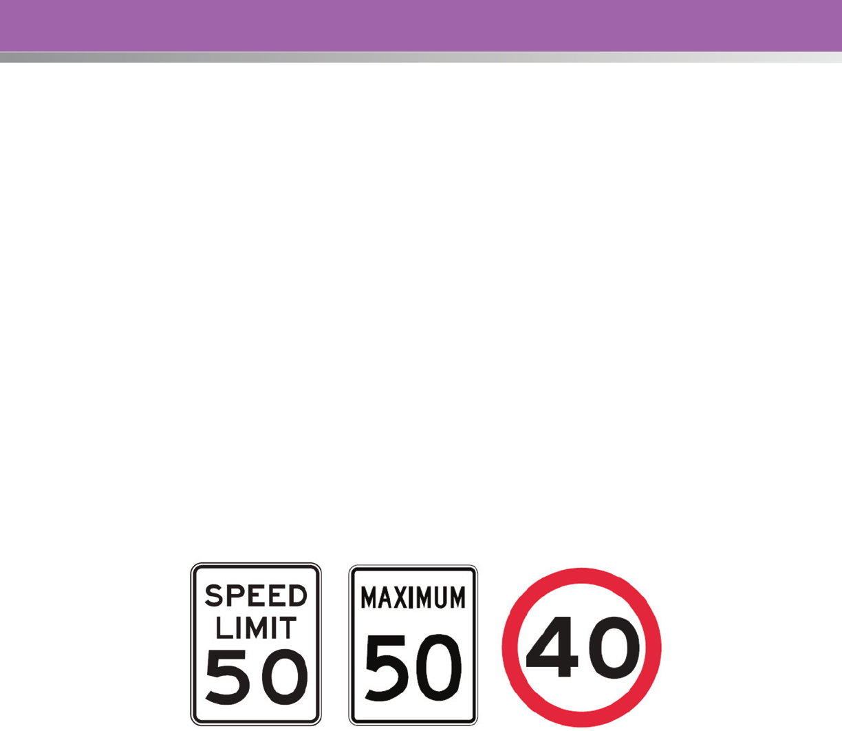
33
Speed Limit Sign Design and Placement
Speed Limit signs must be correctly posted to ensure a speed limit is enforceable and to encourage
compliance. Typical maximum Speed Limit signs are shown in Figure 3. In North America, the latest
editions of the MUTCD and Standard Highway Signs
33
should be referenced when developing signing
for speed zones. The MUTCD contains Standards, Guidance, and Options for the signing, and general
guidelines to follow for the design and layout of the signs are contained in Standard Highway Signs. The
general guidelines show different standard sizes depending on the type of highway or facility where the
sign is intended to be.
In general, Standard Highway Signs states that signs for regulatory speed zones shall be of the
appropriate design—including size, text, and color.
33
The MUTCD states that the speed limits shown shall
be in multiples of 5 mph (8 km/h).
15
Section 2A of the MUTCD discusses standardization of location, mounting height, lateral offset,
orientation, posts, and mountings. Speed Limit (R2-1) signs, indicating speed limits for which posting
is required by law, shall be located at the points of change from one speed limit to another. At the
end of the section to which a speed limit applies, a Speed Limit sign showing the next speed limit shall
be installed. Additional Speed Limit signs shall be installed beyond major intersections, downstream
of egresses from major traffic generators, and at other locations where it is necessary to remind road
users of the speed limit that is applicable. Speed Limit signs indicating the statutory speed limits shall be
installed at entrances to the State and at jurisdictional boundaries of metropolitan areas.
15
In rural areas,
on two-lane highways, Washington State recommends locating Speed Limit signs at 10 to 20 mile
(16 to 32 km) intervals.
34
United States Canada Europe/Australia /United Kingdom
Figure 3. International Speed Limit Signs.
The preferred location for the beginning and ending points of speed zones is where there are definite
changes in the character of the roadside development, like rural and urban boundaries. It is often
desirable to begin and end a speed zone to encompass an important road intersection or driveway of
a major generator like schools or residential developments. It is important to note the location of other
traffic control devices in the segment and coordinate Speed Limit signs with them effectively.
35
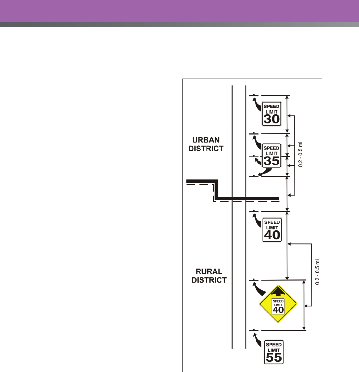
34
For all highways in Washington State, signs for both directions of travel should be located opposite one
another at speed zone boundaries. Furthermore, signs should be installed on both sides of the traveled
way on multi-lane divided highways. If existing highway features prohibit opposite installations, the signs
may be installed a maximum distance of 300 feet
(100 meters) apart, or offset up to 150 feet (50
meters) in either direction from the speed zone
boundary. If these distance parameters cannot
be met, the speed zone boundary may need to
be adjusted to allow for sign installation.
34
Figure 4 illustrates the typical location and
frequency of signs for regulatory speed zones
established by the Texas DOT. Distances shown
between Speed Limit signs are minimums and
may be greater, depending on the results of
speed checks.
19
The following six States offer guidance
concerning repetition of Speed Limit signs:
36
• Alaska: Intermediate Speed Limit signs
should be placed at least once every
two minutes of travel time on urban
roads, and no more than ten minutes
apart on rural roads (except on low
volume rural roads where the signs may
be up to 30 minutes apart).
• Arizona: Where the speed limit is less than
55 mph (90 km/h), the recommended
maximum spacing is given by the formula
S = V/6, where S is the maximum distance
between Speed Limit signs in miles and V
is the speed limit in miles per hour. In rural
areas where the speed limit is 55 mph
(90 km/h) or greater, the formula is
modified to S = V/5.
• California: On freeways with limits of 65
or 70 mph (105 or 110 km/h), spacing is to
be no more than 25 miles (37 km) apart.
Where the freeway speed limit is reduced
to 55 mph (90 km/h), Speed Limit signs are
to be no more than 3 mi (5 km) apart. On
conventional roads, the maximum spacing
between Speed Limit signs is no more than
5 to 10 miles (8 to 16 km).
Figure 4. Example Regulatory Speed Zone Application
Showing Spacing of Signs Transitioning from Rural District
to Urban District and Within the Urban District. (Source:
Adapted from the Texas Department of Transportation.
19
)
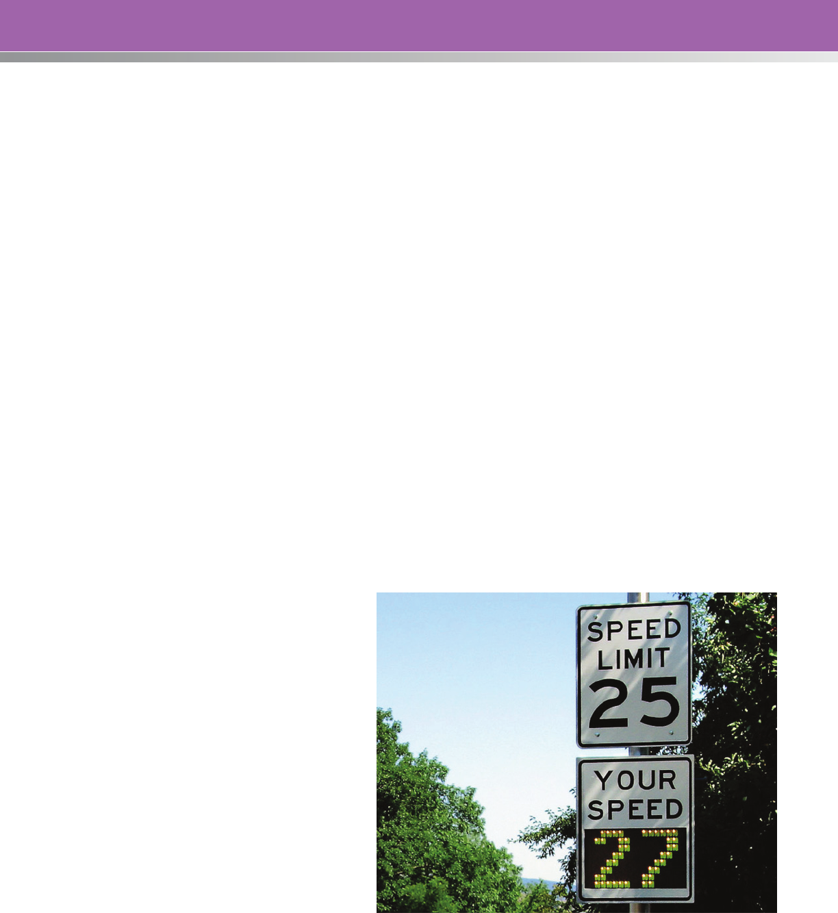
35
• Minnesota: Speed Limit signs are to be repeated at intervals of 60 seconds of travel at the posted
speed where speed is reduced. The repetition may be less in dense urban areas. The maximum
spacing between Speed Limit signs in rural areas is 10 miles (16 km).
• New York: Where a roadway speed limit is restricted relative to the State speed limit, a second
Speed Limit sign is placed within 1100 ft (336 m) of the first. Subsequent Speed Limit signs are to be
no further apart than 100 times the posted speed limit (e.g., for a restricted speed of 35 mph
(60 km/h) the maximum separation is 3500 ft (1068 m)).
• Pennsylvania: Where special speed limits are in effect, the spacing between Speed Limit signs
must be no more than 0.5 miles.
International practices include:
36
• United Kingdom and Ireland: Place Speed Limit signs at approximately half-mile intervals where
speed is restricted to less than the national speed limit for that class of road.
• British Columbia, Canada: On long, uninterrupted sections of rural highways, it is recommended
that Speed Limit signs be repeated at least every 9 to 12 miles (15 to 20 km). Additionally, a
repeater Speed Limit sign should be placed 1000 to 2000 ft (300 to 600 m) downstream of
wherever the speed limit changes.
Speed Feedback Signs
A Speed Feedback sign (also called a driver feedback sign, or variable message sign) is an interactive
sign, generally constructed of a series of light emitting diodes (LEDs), that displays actual vehicle speed
to drivers as they approach the sign (see Figure 5). The purpose of this sign is to reduce vehicle speeds
by making drivers aware of their
speed relative to the posted speed
limit.
30
Studies have found that Speed
Feedback signs can be effective in
reducing mean and 85th percentile
speeds in a variety of situations.
If used, the changeable message
sign legend should be “YOUR SPEED
XX MPH” or similar wording. The
legend should be yellow on a black
background or the reverse of these
colors. Installation of a Speed Feedback
sign is optional, but if used it should be
installed in conjunction with a Speed
Limit sign.
15
Speed Feedback signs are particularly
useful at speed reductions where drivers
have been traveling for some time at a
higher speed. The phenomenon known
as “speed adaptation” causes drivers
Figure 5. Speed Feedback Sign. (Source: Richard Drdul)

36
to underestimate their actual operating speeds in these instances, and the Speed Feedback sign can
assist them in achieving the necessary speed reduction.
Speed Feedback signs may be permanent or temporary installations. However, permanent installations
are usually restricted to selected locations since a proliferation of Speed Feedback signs could lessen
the effectiveness of the signs when they are needed most.
Speed Feedback signs typically operate as follows:
• A blank display is shown when no vehicles are approaching the sign.
• An approaching vehicle’s speed is displayed as a solid numeral (non-flashing numeral) if the
approach speed is at or below the posted speed limit.
• The approach speed is shown as a flashing numeral if the approach speed exceeds the posted
speed limit by 3 mph (5 km/h) or more.
• To discourage racing, the sign must be programmed to not display speeds that are well in excess
of the posted speed limit. In these instances, the sign is most often blank. The maximum speed
that a Driver Feedback sign may display is outlined in the table below:
Table 8. Maximum Speeds to Trigger a Speed Feedback Sign
Posted Speed Limit, mph (km/h) Maximum Speed Display Threshold, mph (km/h)
20 (30) or less 30 (50)
25 (40) 35 (60)
30 (50) 50 (80)
35 (60) 55 (90)
45 (70) 70 (110)
50 (80) 75 (120)
55 (90) or more 80 (130)
Source: Alberta Transportation
37
Speed Feedback signs are most effective when combined with enforcement activities.

37
Speed Study Data Collection
Data collection is an integral part of setting speed limits. Adequate planning and coordination must
occur to ensure the data collection process is as complete, efficient, and effective as possible. This
section describes typical activities that highway agencies will undergo to plan and implement a
data collection effort. Several types of data, including speed, crash, and roadway environment
information, are vital to this process. The ITE Manual of Transportation Engineering Studies
44
provides
guidance in this regard.
The data collection requirements depend on the methodology selected by a jurisdiction in setting
posted speed limits. The Safe Systems approach, for instance, requires very little data collection since it
is based on very basic road design parameters (e.g., number and frequency of accesses, presence of
a raised median, etc.) and general traffic characteristics (e.g., type and frequency of road users). The
data collection effort is relatively minor.
The Optimal Speed Limit methodology has a more intensive data collection effort. While the data
required for the particular roadway under study is generally manageable, there is a large volume of
local data that is required to calibrate the prediction equations and models that are used assessing the
societal impacts of the different speed limit alternatives. A discussion concerning the models and their
calibration is beyond the scope of this document. Project-specific data that is required as input to these
models is detailed in the following subsections of this chapter.
The remainder of this chapter describes the collection process for data that is most often used in the
engineering and expert systems methodologies. The exact data needs are determined by the method
employed by the road authority—more or less data than described herein may be required.
Data Collection Planning and Coordination
Speed zoning studies are conducted to evaluate safety issues and identify appropriate speed limits
for specific roadway segments. In addition to actual travel speeds, there are several other types of
information that may be appropriate input to the process of setting speed limits. Therefore, coordination
within an agency performing the study and with other agencies that may have additional information
may be needed to ensure all the appropriate inputs are considered. Crash data, recent and planned
roadway or adjacent land use changes, and even anecdotal information can be obtained from safety,
planning, enforcement, and other stakeholders. The data collected will be used to examine the speeds
of free-flowing traffic, as well as information on roadway geometry, crash characteristics, land use, and
access. The studies provide details regarding some or all of the following:
• Average annual and hourly vehicular, bicycle, and pedestrian traffic volume.
• Traffic speeds for each flow direction by hour of day.
• Road design elements that may be crash factors, such as horizontal and vertical road curvature,
access points, drainage, pavement condition, sight distance restrictions, roadside objects,
signage, markings and delineation, etc.
• Road lighting and traffic control devices, including signals, signal timing, and STOP signs.
• Summary of crashes and crash causes over a multiyear period.

38
• Plans for expected new development, changes in the type of development, or major closing of
existing development that may change the traffic flow characteristics in the future.
• Recommendations for the speed limit.
19
When planning the data collection activity, it is important to document and control any aspect of
the collection that might have an impact on the measured speed. Measurable physical features,
roadway surface characteristics and conditions, and traffic characteristics and control are items to be
inventoried. If conditions are not relatively consistent throughout the zone under study, consideration
can be given to splitting the study area into shorter sections. For example, if the road transitions from a
2-lane to a 4-lane divided facility, or from on-street parking to no parking, or from rural agricultural land
use to a commercial or residential land use, then speed samples are typically taken in each section.
Factors such as roadway lighting and delineation are reflective of road geometry and land use, but are
not necessarily factors that warrant splitting a study area into shorter sections.
Variables considered for documentation of the site include (but may not be limited to):
• Location and roadway configuration.
• Lanes, delineation, shoulders, medians, grade separation, roadside objects, driveways or
entrances, curvature or grades, lighting, etc.
• Posted speed limit.
• Weather (limiting measurements to fair weather is preferable).
• Direction.
• Restricted sight distance.
• Pedestrian activity.
• Cyclist activity.
• Date and time (in a common format among collections).
• Traffic control devices (regulatory and warning).
• Type and condition of pavement surfaces.
• Businesses, advertising, or residential developments.
• Proximate schools and school routes.
• Surrounding area changes in travel habits or influences.
• Vegetation changes.
In most instances, the variables collected by a particular road authority are dependent on the
methodology used in that jurisdiction to set speed limits, the expected effect of the variable on
operating speeds, and available resources.

39
When undertaking data collection efforts, it is important to understand if there are activities or
conditions outside of the study area that may affect measurements, including construction or
maintenance activities in the area, road closures, detours, the presence of enforcement, and whether
proximate schools are in session.
Study Area
A speed zone study can be initiated in response to a public request for a speed limit review, as a result
of network screening (for crash prone locations), or for any other reason. In all situations, a general study
area is identified through the initial request or data analysis. The study area can then be divided into
homogeneous sections for analysis. A homogeneous section is one where:
• The roadside development is consistent (residential vs. commercial; type and frequency of
businesses and driveways, etc.); and
• The roadway features are consistent (lane widths, medians, shoulders, surface roughness,
curvature, intersection spacing, etc.).
The data collection area will typically extend 500 feet beyond each end of the proposed speed zone
in order to include nearby features. These features will help to determine the homogeneity of the
proposed speed zone, and whether the study area limits should be extended. It may be helpful to take
photographs of features in the intended speed zone and the extended study area, as they may be
helpful in describing any concerns within the study area.
A scaled area map, sketch, or aerial view is usually developed to show the study area and the field
conditions. Generally, a speed zone study used to support a request for alteration of a speed limit
would include this exhibit to identify the location of the proposed zone and any features of interest.
A strip map, or line diagram, is an example of an appropriate format for the exhibit, and details the
information that can be shown on the map. The data points can be collected using a Geographic
Information Systems (GIS) unit, which helps improve the accuracy of the strip map. Figure 6 shows an
example of a strip map that is appropriate for a speed zone study. Table 9 shows the information that
should be shown on a strip map.
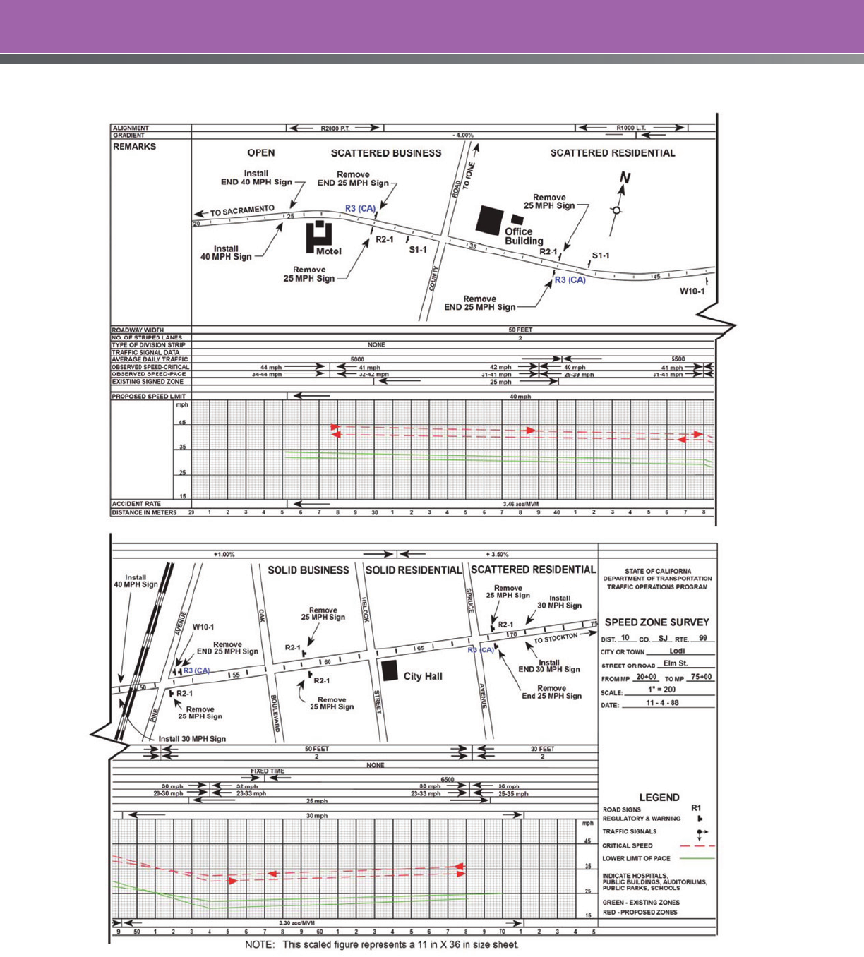
40
Figure 6. An Example of a Strip Map of a Study Area Showing Existing Conditions. (Source: CalTrans, 2009)

41
Table 9. Information to Show on Strip Map
Information Item Notes
Name and highway number of the
route to be zoned
Show all names and/or highway numbers.
Indicate sections to be zoned with a wide center line on the
strip map.
Cross section Width of the roadway/lanes.
Pavement markings.
Number of lanes.
Parking restrictions.
Crossroads, cross streets, and driveway
access points
Show all names and highway numbers.
Limits of the speed zone Indicate reference marker, milepoint, control, and/or section
numbers.
Adjoining speed zone(s) of connecting
map(s)
Note speed limit information for adjoining roadway sections.
Limits of any incorporated city or town Show reference marker, milepoint, control, and section numbers.
Names and approximate limits of the
developed area of unincorporated
towns
Indicate by “Beginning of Developed Area” and “End of
Developed Area” under the heading, “Development”—
not as “City Limits.”
Urban districts Indicate any urban district clearly under the heading
“Development.”
The territory contiguous to and including any highway or
street which is built up with structures devoted to business,
industry or dwelling houses, situated at intervals of less than
100 feet for a distance of 0.25 mile or more on either side.
Schools and school crossings Show schools abutting the highway and those in the vicinity
of the highway.
Show location of schools.
Show all school crosswalks.
Traffic signals Show location of existing devices to aid in proper spacing
and placement of speed zone signs.
Important traffic generators Show all factories, shopping centers/malls, and any other
establishments that attract large volumes of traffic.
Ball bank readings Show readings for each direction of travel for all curves.
Railroad crossings Indicate the number of tracks and type of grade crossing
protection (crossbucks, cantilevers, crossbucks with signals,
gates).
Show the name of the railroad at each crossing.
Bridges Indicate if the roadway on the bridge is narrower than the
roadway on either side of it.
Source: Adapted from the Texas Department of Transportation.
19

42
Speed Data Collection
The result of the speed data collection effort is an accurate picture of the range of vehicles and driver
behavior in the study area. In addition to collecting spot speeds of vehicles traveling through the study
area, test runs can be used to confirm free-flow speeds and compare study area speeds to adjacent
areas outside the speed zone. These data, combined with other crash, roadway environment, and
enforcement information, feed into the data analysis and the determination of the speed limit as
discussed in the next section.
Vehicle Speeds
A variety of methods are available to measure speeds. These methods can generally be grouped into
three categories based on the installation location of the collection equipment:
• Manually-operated, handheld devices that are portable and can be used in most places
(e.g., stopwatch, radar gun, and lidar gun).
• In-road devices that are installed into or on top of the roadway surface (e.g., pneumatic road tube).
• Out-of-road devices that are installed overhead or to the side of the roadway surface
(e.g. radar recorders).
The advantages and disadvantages for several common speed collection devices are shown in Table 10,
and should be considered when selecting a device for use at a particular location.
Ideally, data collection:
• Uses techniques that capture typical traffic behavior without affecting it.
• Collects free-flow vehicles and ignores platoons (less than 5 seconds separation from the vehicle
ahead
*
).
• Collects vehicle type along with the speed so that speed profiles for different vehicle types can
be identified, if desired.
The vehicles checked should be only those in which drivers are choosing their own speed or are free-
flowing. When a line of vehicles moving closely behind each other passes the speed check station, only
the speed of the first vehicle is checked, since the other drivers may not be choosing their own speed.
Vehicles involved in passing or turning maneuvers are not to be checked, because they are probably
driving at an abnormal rate of speed. Turning lanes, or other special lanes, are not normally used to
collect speed data.
*
Some analysts prefer to discard a speed measurement if a vehicle is following another vehicle within five seconds, as the lead
driver may be slower than they would ordinarily be traveling in an open road situation.

43
Table 10. Advantages and Disadvantages of Speed Collection Devices (Adapted from Reference 43)
Method
Data
Collected Labor
Equipment
Cost* Advantages Disadvantages
Radar
Recorders
Instantaneous
speed, traffic
volumes,
vehicle class,
traffic flow
gaps**
Low High Little labor required to
collect and tabulate data:
can collect data for long
periods of time; other
traffic-related data may
be collected at the same
time; can be used when
snowplows may be present
without risk of damage;
less visible to traveling
public than road tubes
User cannot randomly
select vehicles for data
set; some devices
may not accurately
collect data for multi-
lane roadways and/or
determine directionality
of observed vehicles;
equipment-intensive
method; maintenance/
calibration required
Pneumatic
Road Tube
Instantaneous
speed, traffic
volumes,
vehicle class,
traffic flow
gaps**
Low Medium Little labor required to
collect and tabulate
data; can collect data for
long periods of time; other
traffic-related data may
be collected at the
same time
Visible to traveling public
which may change
driver behavior; user
cannot randomly select
vehicles for data set;
use discouraged when
snowplows may be
present; most equipment-
intensive method;
maintenance/calibration
required
Laser Gun Instantaneous
speed
Medium High Equipment is easily
portable; user controls
vehicles sampled as
a more focused laser
beam limits the number
of readings for non-target
vehicles as compared to
radar
Cosine error limits
horizontal/vertical
deployment; scopes and
sights may not be user-
friendly; laser beams more
sensitive to environmental
variances than radar;
maintenance/calibration
required
Radar Gun Instantaneous
speed
Medium Medium Equipment is easily
portable; user controls
vehicles sampled;
accurate data collection
method; widespread
equipment availability has
lowered its cost
Cosine error limits
horizontal/vertical
deployment; closely-
spaced and larger
vehicles may create
readings for non-targeted
vehicles; maintenance/
calibration required
Stopwatch Travel time
over a
distance
High Low Little equipment to
purchase and maintain;
easy to perform data
collection process
Labor-intensive; collects
time data that needs to
be converted to speed
data; typically low
accuracy
*Equipment costs reflect the initial purchasing costs of the equipment and not future maintenance and calibration costs.
** The amount of additional data collected varies for each device. Consult the device’s user manual for a better understanding
of the capabilities.
44
Due to different physical and operational characteristics of trucks and buses, data for these vehicles
are usually recorded separately. If separate speed limits are believed warranted for large trucks or other
vehicle classifications, a separate count and analysis of these vehicles may be needed.
Data collection forms help organize data for the spot speed study. Appendix G (Example Speed Study
Forms) contains a sample “Vehicle Spot Speed Study” data collection sheet from the Florida DOT.
30
The speed profile for a particular road section can only be estimated by measuring individual speeds
through a spot speed study. Prior to conducting these studies, the minimum number of vehicles for
which speed data are needed to sufficiently estimate speed parameters should be estimated. The
minimum number of vehicles required to accurately estimate the speed profile is dependent on the
level of confidence required for the statistical analysis of the data. The ITE Manual of Transportation
Engineering Studies
44
presents the following equation to calculate the minimum sample size for
estimating the 85th percentile speed:
Where:
N = minimum number of measured speeds
S = estimated sample standard deviation, mph
K = constant corresponding to desired confidence level
U = constant corresponding to the desired percentile speed
E = permitted error in the speed estimate, mph
The Manual of Transportation Engineering Studies provides tables for determining the values for S, K,
and U. Table 11 shows an example sample size calculation for estimating the 85th percentile speed,
using this formula.
44
Table 11. Example Calculation of Sample Size for Study to Determine 85th Percentile Speed
Assumptions:
The average standard deviation is rounded to 5.0 mph S = 5.0 mph
The desired confidence level is 95 percent K = 1.96
The study will determine 85th percentile speed U = 1.04
The permitted error is 2 mph E = 2 mph
Calculation:
Sample Size N = 37
Analysis:
Using a sample size of 37, the 85th percentile speed can be determined within 2 mph at a 95 percent
confidence level.

45
Performing the same calculation with a permitted error of 1 mph (E = 1 mph) results in a sample size of 148.
A common sample size for many jurisdictions is 100 vehicles. Assuming a standard deviation of 5 mph, and
using a 95 percent level of confidence, the 100 vehicle sample size will yield between a 1 and 2 mph error in
the 85th percentile speed, and it makes calculation of the 85th percentile fairly simple (refer to Appendix H).
Table 12 lists the sample sizes and sample periods used by three States. Most States use 100 or more
vehicles in each direction for each station. Since meeting the minimum collection data on low-volume
roads can be difficult, adjustments on the sample size can be made based on the duration of the
collection period. On highways carrying low traffic volumes, the speed checks at any one station are
usually discontinued after two hours, even if a minimum of 100 vehicles have not been recorded.
Table 12. Sample Sizes and Data Collection Periods Used by Three States
State Sample Size Exceptions
MASSACHUSETTS
18
100 or more vehicles in each
direction should be checked at
each station.
On highways carrying low traffic
volumes, the checks at any one
station may be discontinued after
two hours although a minimum of 100
vehicles have not been timed.
OHIO
29
Record speeds of 100 vehicles for
each direction of travel.
Observation need not exceed one
hour even if less than 100 vehicles are
recorded traveling in each direction.
TEXAS
19
A minimum of 125 cars in each
direction, at each station.
Discontinue after two hours if radar
is used, or after four hours if a traffic
counter that classifies vehicles by type
is used—even if 125 cars have not
been timed.
The
Manual of Transportation Engineering Studies
formula for determining a spot speed sample size
is premised on a random sample of vehicles over the course of the time. Since the analyst is usually
stationed at the study site for a limited time, the speed data is actually assembled from a cluster sample.
Cluster sampling generally increases the variability of sample estimates above that of simple random
sampling, and for this reason cluster sampling usually requires a larger sample than simple random
sampling to achieve the same level of accuracy. Therefore, sample sizes that are slightly larger than those
predicted by the Manual of Transportation Engineering Studies formula would increase the accuracy of
the 85th percentile speed estimate. Furthermore, the times at which the spot speed sample is conducted
should include observable speeds that are representative of the operating speeds for all times of the day.
If automated collection of speed data is employed, then it is possible to collect data for extended
periods. Collecting data for a 24-hour period will account for variation in traffic patterns and will allow
for determination of different speed limits for different times of the day, if needed. For example, a time-
limited school zone speed limit or a nighttime speed limit.
Care must be exercised when using automated data collection to ensure that only free-flow speeds are
collected, and that data collection units are placed sufficiently far from intersections and other points of
access where vehicles that are accelerating/decelerating may influence the speed profile.
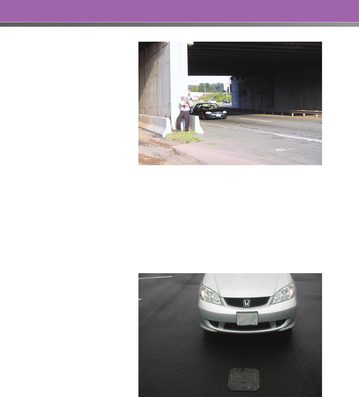
46
Speed check stations need to be
located to show all the important
changes in prevailing speeds. The
data collector should pick a location
that will not influence the behavior
of the drivers. Table 13 shows
recommendations for speed check
stations for three States for both
urban and rural areas. While these
States provide some guidance in the
form of set distances between speed
check stations, it is important to
remember that it is not the distance
between stations that is critical—
rather it is the changes in the road,
traffic, and environment that may
lead to different speed profiles
and operating speeds. Distances
between speed check stations may
be increased or decreased from
those provided accordingly.
Radar speed meters, which operate on the Doppler principle, or lidar, which operates on a laser principle,
are normally used for making manual speed checks. These devices typically operate from the power
of an automobile battery and give direct readings of vehicle speeds which are accurate to within 2
mph (3 km/h).
19
The operating instructions for the radar unit will provide factors for calibration, optimum
distance of survey, and optimum angle of survey. Speed measurement should be done in an unobtrusive,
undetectable manner so as to obtain a sample of normal traffic speeds. If the radar operation is detected
by drivers, there is the potential for the data to be biased as drivers change their speeds.
45
Figure 7 shows
an example of a radar operation
setup.
Automatic speed classification
equipment technology may be used
in determining vehicular speeds for
use in calculating 85th percentile
speed. Examples of technologies are
counter-classifiers with the capability
of classifying vehicles, determining
vehicular speeds, and differentiating
the gap between vehicles. These
devices may include video imaging,
tube counters, magnetic counters,
inductive counters, etc.
19
Figure 8
shows an example of a portable
traffic analyzer. With automatic data
collection equipment, speed data is
normally collected at sites for at least
a 24-hour period.
Figure 7. Radar Setup.
Figure 8. Portable Traffic Analyzer.

47
The reason for collecting spot speed data is to estimate the free-flow speed of a facility for use in setting
speed limits. Ordinarily, it is only necessary to collect spot speed data once during the time-of-day,
and the day-of-week that will yield the best estimate of free-flowing speeds. Collecting speed data
at more than one time-of-day or day-of-week is dependent on the analyst’s confidence in the single
measurement representing the true free-flow speed for the facility. Additional spot speed studies at a
single location may also be conducted if the analyst is considering a variable speed limit, or a speed
limit that is time-limited (i.e., a school zone speed limit).
Table 13. Speed Check Stations for Three States
State Speed Check Station Layout Information
MASSACHUSETTS
18
URBAN • Speed check stations should be strategically located to show all
the important changes to municipalities; speed check stations
should generally be located at intervals not to exceed 0.25
miles, depending upon the locality and the uniformity of physical
and traffic conditions. Much closer spacing than this may be
necessary to obtain an accurate picture of the speed pattern.
RURAL • In rural areas, the spacing of speed check stations may be at
much greater intervals provided they properly reflect the general
speed pattern. There should be at least one observation for each
direction of travel in each zone of a different numerical limit.
OHIO
29
• Speed checks may be taken with any device that will indicate
vehicle speed with an accuracy of +/-10 percent.
• Speed checks should be taken at the 1/3 point (total of four
checks) for zones 0.25-1.00 mile in length, and at 0.5-0.75 mile
intervals for zones over 1 mile in length.
TEXAS
19
URBAN • Should generally be located at intervals of 0.25 mile or less if
necessary to ensure an accurate picture of the speed patterns.
• Should be located midway between signals or 0.2 miles from any
signal, whichever is less, to ensure an accurate representation of
speed patterns.
• Should take into account locality, and the uniformity of physical and
traffic conditions may be determined by trial runs through the area if
volumes are too low or if a recheck of speeds is all that is needed.
• Should be checked midway between interchanges on the main
lanes of expressways and freeways.
RURAL • May be at intervals greater than 0.25 mile, as long as the general
speed pattern is followed and may only be necessary at each
end and the middle point if the characteristics of the roadway
are consistent throughout the entire section.
• May be determined by trial runs through the area if the
characteristics of the roadway are consistent throughout the entire
section and a speed check in that section indicates that 125 vehicles
cannot be checked within the two hours if radar is used, or after four
hours if a traffic counter that classifies vehicles by type is used.

48
Speed Test Runs
The purpose of the test runs is to generate an operating speed profile and ensure that measured spot
speeds are representative of speeds throughout the section.
The general idea is to perform several runs at free-flow speeds as a way to confirm the speed data
collected for use in determining 85th percentile speed and compare spot speeds to the test run speeds
for the full study section. When planning test runs, in general:
• Test runs should be made by driving as fast as it is comfortably safe.
• Test runs should be made so that other traffic will not delay the test car.
• The speed should be recorded at a range of 0.10 to 0.25 mile (.15 km to .45 km) interval or more.
• The average speed of three test runs should be determined in each direction.
29
An alternative methodology for conducting a speed test run is the floating car method, i.e., following
cars and recording their speeds or journey times through the study area. This method allows an
assessment of a driver’s free-flow speed, and not the desired speed of the person conducting the
survey (as this might differ from the general population).
To counter arguments that the 85th percentile spot speed studies are not representative of the
operating speeds along the entire street, a test run speed profile can be combined with the spot 85th
percentile speeds to obtain an 85th percentile speed profile.
51
The speed profile is established by an
individual driving the road in his or her usual manner, while an observer records the time for the vehicle
to travel a set interval (e.g., 100 m). Then the following procedure can be used to develop an 85th
percentile speed profile (the data in Table 14 is referenced to demonstrate method):
• For each location where a spot speed is measured, comparison factors are calculated by
dividing the 85th percentile speed by the test run speeds and the average test run speeds for
the same location. In the example, there are two locations where spot speeds were measured—
Station 0+600 and Station 1+600.
• The variation of comparison factors for each test run is determined separately. In the example,
there are only two comparison factors for each test run, so the difference between the two
factors is used as the measure of variance.
• The comparison factors for the test run with the lowest variation are then averaged and this
average factor becomes the correction factor. In the example, Test Run 1 has the lowest
variation.
• The average test run speed for each location is multiplied by the correction factor to yield an
estimated 85th percentile speed for each location.
51
49
Table 14. Example of Using Speed Test Runs to Confirm 85th Percentile Speeds (km/h)
Test Run Comparison Factor
Station
Spot
Speed 85th
Percentile 1 2 Average 1 2 Average
Estimated
85th
Percentile
Speed
0+000 85 86 86 88
0+200 87 86 87 89
0+400 84 79 82 84
0+600 83 80 88 84 1.038 0.943 0.988 86
0+800 82 84 83 85
1+000 80 78 79 81
1+200 75 78 77 78
1+400 62 63 63 64
1+600 71 70 66 68 1.014 1.076 1.044 70
1+800 69 71 70 72
2+000 72 70 71 73
Variation
0.023
0.133 0.056
Correction
Factor
1.026
Data Analysis
The ITE Traffic Engineering Council Technical Committee surveyed the speed zoning practices used by
agencies across the United States. The committee collected speed zoning guidelines from 40 States and
conducted 124 surveys with ITE members serving as traffic engineers in State and local agencies. Based
on the results of the survey, the most important factors considered for recommending a speed limit are:
85th percentile speed; followed by roadway geometry, crash exposure, and roadside development.
17
This section discusses the compilation of speed and crash data used to develop the inputs to the speed
limit setting process.
85th Percentile Speed
The Manual on Uniform Traffic Control Devices (MUTCD) lists the current speed distribution of free-flowing
vehicles as a primary factor to consider when establishing speed limits. The MUTCD also states that the
speed limit should be within 5 mph (8 km/h) of the 85th percentile speed.
15
The 85th percentile speed is the speed at or below which 85 percent of the free-flowing vehicles
travel, and has traditionally been considered in an engineering study to establish a speed limit. Traffic
engineers have assumed that this high percentage of drivers will select a safe speed on the basis of the
conditions at the site. The 85th percentile speed is considered the first approximation for the speed limit.
The Ohio Department of Transportation collects vehicle speeds even if it is not possible to observe free-
flow conditions. Then the 85th percentile speed of all vehicles is increased 5 to 10 mph (8 to 16 km/h) to
approximate the free-flow 85th percentile speed. If the 85th percentile speed of several speed checks varies
considerably, the 85th percentile speeds are averaged, or the most representative speed is selected.
19

50
A convenient way to determine speed percentiles is a frequency distribution table. An example, with an
explanation of how to use it, is provided in Appendix H.
10 mph (16 km/h) Pace
The speeds of individual vehicles on a highway vary. Speed dispersion refers to this spread in vehicle
speeds. The 10 mph (16 km/h) pace is the ten mile-per-hour range of speeds containing the greatest
number of observed speeds and is a measure of speed dispersion. It is described by both the speed
value at the lower end of the range and the percentage of all vehicles that are within the range; and,
thus, is an indicator of speed dispersion.
A normal speed distribution contains approximately 70 percent of the vehicles within the pace, with
approximately 15 percent of the vehicles below and 15 percent above the limits of the pace speed.
The upper limit of the 10 mph (16 km/h) pace speed is therefore approximately the 85th percentile
speed in most cases. However, the upper limit of the pace speed may vary from the 85th percentile
speed, depending on the distribution curve of the vehicle speeds.
There is general agreement that the safest conditions occur when all vehicles at a site are traveling at
about the same speed.
11
Crash Data
Crash data are typically considered in establishing speed limits. The factors potentially contributing to
the crashes should be examined to determine whether speeding was involved, or whether the speeds
were too high for a specific condition or feature. Speed contributes to the severity of a crash, and sites
with a history of severe injury or fatal crashes may be locations with high levels of speeding. The National
Highway Traffic Safety Administration (NHTSA) considers a crash to be speeding-related if the driver
was charged with a speeding-related offense or if an officer indicated that racing, driving too fast for
conditions, or exceeding the posted speed limit was a contributing factor in the crash.
46
Crash data may be accessed via State, local, county or community-wide databases. These
databases may be housed within State agencies including the Department of Safety, Department
of Transportation, or State Highway Patrol, within local law enforcement agencies, or within the court
system. In some cases there may be some information missing from the database. For example, if a
database is not GPS-based, or does not include detailed information regarding the location of a crash,
it may be difficult to locate the site. In some communities the data is still maintained in paper format,
and manually reviewing paper records is time consuming and costly. Coordinating field data collection
and crash analysis prior to the start of the program is one way to minimize costs.
A review of crash data can show whether the study area has a higher than average crash experience,
and whether the portion of crashes that appear to be related to speeding is higher than average. The
MUTCD recommends reviewing reported crash experience for at least a 12-month period.
15
Twelve
months is considered a short-term crash count and is insufficient as a basis for making sound safety
decisions. The implications of crash frequency fluctuation and variation of site conditions are often
in conflict. On one hand, the year-to-year fluctuation in crash frequencies tends toward acquiring
more years of data to determine the expected average crash frequency. On the other hand,
changes in site conditions can shorten the length of time for which crash frequencies are valid for
considering averages. This conflict between crash data variations and changing site conditions requires
considerable judgment in selecting an analysis period.
Typically, road authorities review crash data for a three- to five-year period.

51
When crash data are collected, it is important to consider the following factors before interpreting
existing data or gathering new data:
• Only consider data collected on road segments that are within the study area.
• Gather categorized details about the site geometry, traffic control devices, signage, weather,
lighting conditions, time of day, day of week, interaction with other vehicles, etc.
• Minimize the amount of emphasis placed on individual (severe) crashes rather than trends or
clusters of crashes.
• Differentiate between mid-block and intersection crashes.
• When comparing crash datasets, ensure that the same filtering criteria are used to develop the
datasets.
• Watch for data format issues between data sources and collection periods to avoid difficulties in
coding and analysis.
• Although data should be sanitized for driver identity before reporting, maintaining a link to the raw
data source until the data is ready to be published or used for the last time will make it possible to
go back to the source easily to supplement and verify details for analysis and report generation.
• Note extenuating circumstances that may preclude or overshadow typical trends and analyses
and be prepared to filter or caveat them (e.g., long-term construction zones, new developments,
major changes or reconstruction, etc.).
Some measure of the crash experience of the study site can be developed and compared to the
average of that measurement for similar sites in a jurisdiction. Examples are crash frequency, crash
density, and crash rate. Some agencies factor crash severity into safety analyses by giving a higher
weight to injury and fatal crashes. The average of this frequency, rate, or other measure, for all
roadways of a similar type (such as urban 4-lane undivided arterials) in a State would be a good value
for comparison. A discussion of how the analyzed data are used in determining speed limits is presented
in the next section.
Isolating the effect of one crash factor, such as speed, can be a challenge. Often it is difficult to identify
the role of speed in crashes, and for this reason it is thought that speed-related crashes are often under-
reported.
47
For this reason, all crashes may be considered in setting speed limits.
A crash diagram is often prepared as a part of the safety analysis to help identify patterns and trends in
the crash data.
The state-of-the-art in crash data analysis and determining the safety performance of a facility is
contained in the Highway Safety Manual. This document provides analytical tools and techniques for
estimating the expected crash risk of different facilities, and it can also be used in assessing the safety
effects of a change in the posted speed limit.

52
SPEED LIMIT ENFORCEMENT
While a properly selected speed limit is hopefully self-enforcing, the reality is that an effective speed limit
generally relies in part on enforcement of the limit. The engineering community has four main roles in
speed enforcement:
• Communicate with those responsible for enforcement during the setting of speed limits;
• Provide data to enforcement officials so they may effectively deploy enforcement resources;
• Provide and maintain automated speed enforcement (ASE) equipment and technologies (where
allowed); and
• Integrate features in the road design to facilitate speed enforcement (i.e., laybys and median
openings that assist enforcement personnel).
Because speed limits and enforcement are intertwined, it is important for the road authority to liaise
with enforcement personnel before setting a speed limit for a facility. Enforcement personnel have
experience and unique insights into the enforceability of speed limits that may be used to ensure that
rational speed limits are applied.
Speed enforcement is essentially a crash countermeasure and therefore benefits from a proper
understanding of the persons, place, time, and conditions that foster speeding. Engineering personnel
can provide speed and crash data as well as citizen complaints to enforcement personnel so that
appropriate enforcement strategies are identified. This data-driven approach to resource deployment
can target specific scenarios of speeding or types of speeding activities (e.g., commuters, after-school,
racing, deliveries, etc.).
Automated speed enforcement uses equipment to monitor speeds and photograph offenders to
produce citations that are mailed to the registered owner of the vehicle. ASE is particularly effective
at locations where the roadway geometry or traffic volumes make it difficult to use more traditional
methods (e.g., requiring a traffic stop). This strategy requires enabling legislation, if such legislation has
not already been passed. NHTSA’s Speed Enforcement Camera Systems Operational Guidelines is a
useful reference.
48
The engineering community is generally involved in ASE, as it requires speed cameras that are
maintained by the road authority. In all cases, enforcement personnel need to be involved and an
integral part of any ASE activities.
A combination of the various enforcement strategies described above, in addition to engineering and
communications countermeasures, may contribute to ongoing compliance with the speed limit. When
an effective speed enforcement program is sustained, it can continue to deter speeders. The NHTSA
and FHWA Speed Enforcement Program Guidelines is a useful reference.
42

53
CASE STUDIES
To demonstrate the application of some of the principles and methods presented in this informational
report, two case studies are presented. The case studies use existing roads and real data. In both
cases, the posted speed limit is determined by the engineering, expert system, optimal speed, and safe
systems methods. It is noted that not all of the data was collected for each of the methods, and for the
sake of presenting each of the speed limit setting methods, reasonable assumptions were made about
some values.
The outcomes may or may not match with the actual posted speed limit as determined by the
governing road authority. This does not suggest that the road authorities are using outdated or incorrect
methods in setting their speed limits. On the contrary, the methods used to set the initial and/or revised
speed limits were in compliance with State statutes and requirements and the guidance provided in the
federal MUTCD.
It must be remembered that in all speed limit setting studies, the tools and techniques that are available
to the practitioner are intended to assist the practitioner in making a decision—it is guidance and not
direction as to the speed limit to be posted. Engineering judgment must be applied.
54
CASE STUDY 1: Urban Collector Road
As part of a speed limit reevaluation process, the City of Palm Bay, Florida, identified Eldron Boulevard
from Jupiter Boulevard to Raleigh Road for analysis. The study area was selected based on the following
considerations:
• The roadside development is consistent throughout the study area;
• The physical features of the road are consistent throughout the study area; and
• The study area is bounded by signalized intersections at both ends of Eldron Boulevard, which
form a natural break-point for speed zoning.
Eldron Boulevard is a north-south collector road approximately 2.3 miles long and located in a
northeastern portion of the City. The study segment is essentially straight and flat, with a design speed of
50 mph or more. It is a two-lane, undivided facility with no shoulder and an 8-foot wide sidewalk on the
east side of the road, located about eight feet from the edge of the pavement. The lane widths are 12
feet each.
The contiguous and surrounding land use is single-family residential. There are 85 single-family residential
driveways, one minor commercial driveway, and 26 two-way, stop controlled intersections that access
Eldron Boulevard. The area is basically fully developed, and traffic volumes are relatively stable over time.
Eldron Boulevard is a municipal transit route. Parking is not prohibited, but happens very infrequently.
Pedestrian volumes are typical for a residential street, and cyclist volumes are considered low. Street
lighting is present throughout the study area.
Given the consistent physical features throughout the study area, a single spot speed measurement
location was deemed sufficient. However, given the length of the study area, and as an extra
precaution, the analysts decided to measure spot speeds at two locations. The spot speed stations
were spaced evenly in the study area, and were located away from intersections or major driveways
that would include vehicles changing speeds while using these accesses. Pneumatic road tubes were
used to collect spot speed data at two locations in the study area; the results are as follows:
North Station South Station
Posted Speed Limit 40 40
Median Speed (50th Percentile) 38.8 37.2
Average (Mean) Speed 39.3 32.2
85th Percentile Speed 43.4 43.0
10-mph Pace 35 – 44 35 – 44
Percent Exceeding the Speed Limit 48.3 32.2
Five test runs were undertaken through the study area, and the average test run speed was 41 mph.
From January 2009 to July 2010 (19 months), there were 19 crashes in the study area. Two of these
crashes resulted in personal injuries, none in fatalities. The average daily traffic volume during this time
was 9200 vehicles per day. The crash rate for this road is 1.55 crashes per million-vehicle-miles (MVM).
The average crash rate for these types of facilities is 2.22 crashes/MVM.
55
Engineering Method Using Operating Speed
Using the Illinois DOT Method
STEP 1: Establish the Prevailing Speed
The prevailing speed is the average of the 85th percentile speed, the upper limit of the 10 mph pace,
and the average test run speed, rounded to the nearest 5 mph increment.
A B C (A+B+C)/3
Station
85th Percentile
Speed (mph)
Upper Limit of the
10-mph Pace (mph)
Average Test Run
Speed (mph)
Prevailing Speed
(mph)
North 43.4 44 41 42.8
South 43.0 44 41 42.7
The prevailing speed rounded to the nearest 5 mph increment is 45 mph for both locations in the study area.
STEP 2: Supplementary Investigations
Adjustment factors for determining the proposed posted speed limit as determined by further
investigation of the following four conditions:
• Elevated Crash Risk: The speed zone being studied has a crash rate of 1.55 crashes/MVM, which
is lower than the statewide average of 2.22 crashes/MVM for these types of roads. Hence, there is
no adjustment required for crash risk.
• Access Control: The access conflict number (ACN) is calculated for the speed zone, based on
85 single–family, residential driveways, one minor, commercial driveway, and 27 two-way, stop-
controlled intersections in the study area:
ACN* Reduction (%)
< 40 0
41 to 60 5
> 60 10
Where:
N
s
= Number of field entrances and driveways to single-family dwellings
N
m
= Number of driveways to minor commercial entrances, multi-family residential units, and
minor street intersections
N
i
= Number of driveways to major commercial entrances, large multi-family developments,
and major street intersections

56
Therefore, based on accesses, it is appropriate to lower the prevailing speed (from Step 1) by 10 percent.
• Pedestrian Activity: The pedestrian activity is typical for a residential area, is accommodated
by a sidewalk on one side of the street, and is not considered “significant pedestrian activity.”
No further adjustment is required for this factor.
• Parking: Parking is negligible and is not a factor in determined the posted speed limit.
The total adjustment from the 4 different factors is 10 percent.
Step 3: Selection of Preliminary Speed Limit
The preliminary speed limit is either the calculated prevailing speed (from Step 1), or if the optional
investigation was undertaken, it is the prevailing speed as adjusted by application of the percentage
corrections from the optional investigation (Step 2). Since Step 2 was undertaken, the preliminary posted
speed limit is:
• 45 mph – (0.1*45 mph) = 41 mph
The following rules apply to the outcome:
• The preliminary posted speed limit should be the closest 5 mph increment to the (adjusted)
prevailing speed. This results in a preliminary posted speed of 40 mph.
• The preliminary posted speed limit shall not differ from the prevailing speed (from Step 1) by more
than 9 mph or by more than 20 percent, whichever is less. This condition is satisfied by the 40 mph
preliminary posted speed limit.
Therefore, the proposed preliminary speed limit is 40 mph.
Step 4: Violation Check
The proposed speed limit should be either the preliminary posted speed limit or the 50th percentile
speed, whichever is greater. In this case, the median speeds are 38 to 39 mph, so the preliminary posted
speed limit of 40 mph is valid.
It is noted that the statutory speed limit for Eldron Boulevard is 30 mph, which is less than the preliminary
posted speed limit determined above. At this point, the road authority has the option of either posting
at the statutory speed, or the proposed speed limit.
The Illinois method of setting speed limits results in a recommended speed limit of 40 mph.
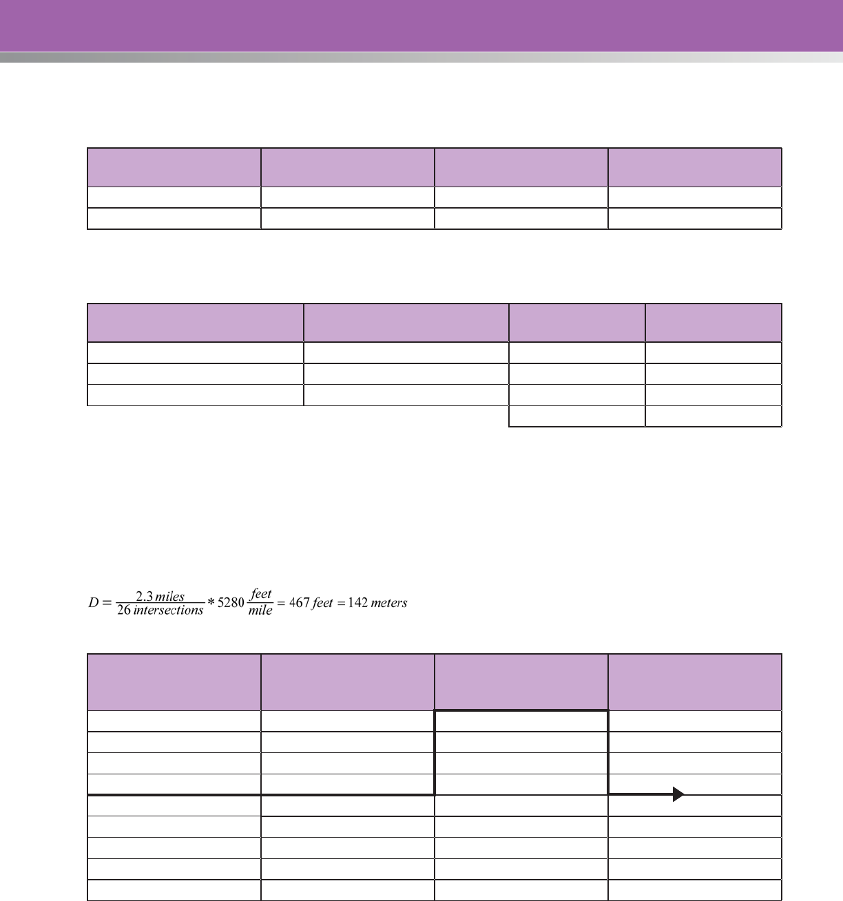
57
Using the Northwestern Speed Zoning Technique
Step 1: The Minimum Speed Study
Station
85th Percentile Speed,
km/h (mph)
Upper Limit of the 10-
mph Pace, km/h (mph)
Average Test Run Speed,
km/h (mph)
North 43.4 (70) 71 (44) 66 (41)
South 43.0 (69) 71 (44) 66 (41)
For the minimum speed study, speed measurements yield the following:
Criteria
Justified Speed Limit (from
Table 18) Weight Weighted Limit
85th Percentile Speed 70 3 210
Upper Limit of the Pace 70 3 210
Average Test Run Speed 80 4 320
Sum 740
The weighted average is 740/10 = 74 km/h, which suggests a speed limit of 75 km/h based solely on the
speed data.
The suggested speed limit needs to be checked against the major physical features of the road. The
design speed of Eldron Boulevard is 50 mph (80 km/h), and the length of road under study is 2.3 miles
(3.7 kms). The average distance between intersections is:
Design
Speed (km/h)
Average Distance
Between Intersections
(m)
Length of Proposed
Zone (km)
Maximum Speed Limit
(km/h)
110 400 1.5 110
100 300 1.0 100
90 250 0.8 90
90 175 0.7 80
70 125 0.6 70
70 100 0.5 60
50 75 0.4 50
50 60 0.3 40
30 45 0.2 30

58
All three criteria are satisfied by a 70 km/h (45 mph) speed limit. Therefore the minimum study
recommends a speed limit of 70 km/h (45 mph).
Continuing on with the detailed analysis, the factors determined from the various tables are:
Adjustment Factors
Non-commercial Access (Table 20) -5
Commercial Access (Table 20) +5
Lane Width (Table 21) +5
Functional Classification (Table 22) -5
Median Type (Table 23) 0
Shoulder Type and Width (Table 24) 0
Pedestrian Activity (Table 25) -15
Parking Activity (Table 26) 0
Roadway Alignment (Table 27) +10
Crash Rate (Table 28) +10
Totals +30 -25 =+5
The overall adjustment factor (OAF) is +5 which can be used to determine the multiplication factor (MF) as:
MF = (100+OAF)/100 = (100+5)/100 = 1.05
The multiplication factor is less than 1.25 and greater than 0.75; therefore, the recommended speed
limit (SL) is the speed limit from the minimum study multiplied by the multiplication factor and rounded to
the nearest 10 km/h:
SL = 70 km/h * 1.05 = 73.5 km/h ➞ 75 km/h or 45 mph
The recommended speed limit based on the Northwestern Speed Zoning method is 45 mph.
Expert Systems Approach Using USLIMITS2
The data from the Eldron Boulevard speed limit study was entered into the USLIMITS2 program
to determine the recommended speed limit for this section of road. The entered data and the
recommended speed limit are shown in the boxed area below. The speed limit recommended by the
USLIMITS2 approach is 40 mph.

59
USLIMITS2 Data Output
Top of Form
Basic Project Information
Project Name – Case Study 1
Project Number –
Project Date – 09-21-2011
State – Florida
County – Brevard County
City – Palm Bay City
Route – Eldron Boulevard
Route Type – Road Section in Developed Area
Termini from – Jupiter Boulevard
Termini to – Raleigh Road
Route Status – EXISTING
Description – FHWA/ITE Informational Report
Case Study
Roadway Information
85th Percentile Speed – 43 mph
50th Percentile Speed – 39 mph
Section Length – 2.30 mile(s)
Statutory Speed Limit – 30 mile(s)
AADT – 9200
Adverse Alignment – No
Lanes and Presence/Type of Median – Two-lane
road or undivided multi-lane.
Number of Lanes – 2
Area Type – Residential Collector
Number of Driveways – 112
Number of Signals – 0
On Street Parking and Usage – Not High
Pedestrian / Bicyclist Activity – High
Crash Data Information
Crash Data Months/Years – 1.58
Crash AADT – 9200
Total Number of Crashes – 19
Total Number of Injury Crashes – 2
Section Crash Rate – 155
Section Injury Rate – 16
Crash Rate Average for Similar Sections – 222
Injury Rate Average for Similar Sections – 73
Comments –
Recommended Speed Limit is: 40
Note:
The final recommended speed limit is higher
than the statutory speed limit for this type of
road. The statutory limit is 30 mph.
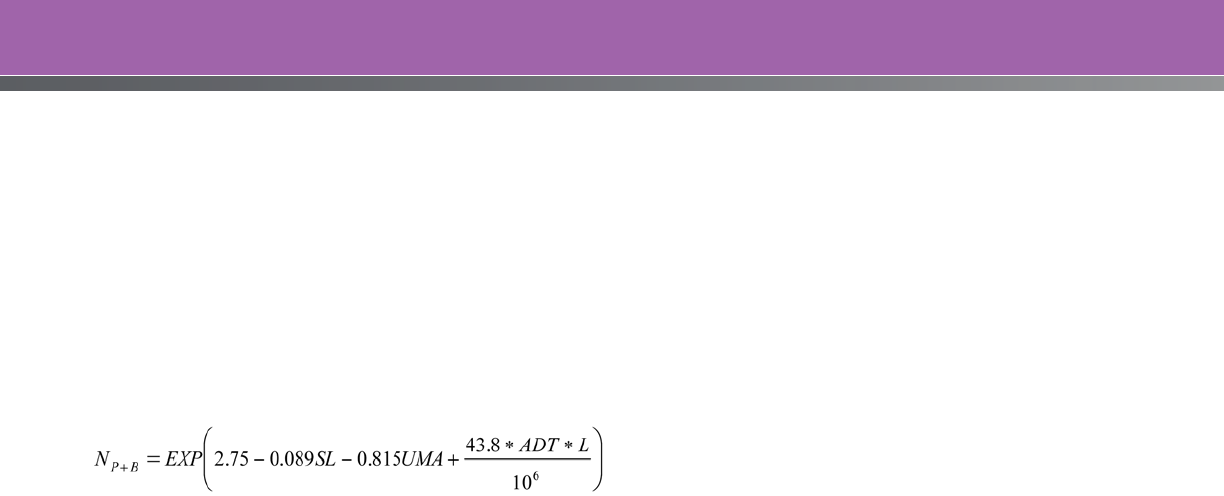
60
Optimal Speed Limit
The optimal speed limit is determined by calculating and selecting the speed that produces the lowest
societal cost. In this case study only crash costs and fuel costs will be considered to demonstrate
the method. In a full analysis, other societal costs would be analyzed, including time travel costs,
automobile emissions, etc.
Step 1: Calculate the Crash Costs
The road authority has developed the following crash prediction models using regression techniques,
traffic, infrastructure, and historic crash data for roads under their control:
(
)
ULUCUMAGMNOLWSLADT
s
XX.EXPN
vv
5.219.142.038.019.00069.0026.0000014.071.013.0950 −−−−+−−+++
=
−
Where: N
P+B
= Number of pedestrian and bicyclist crashes per year, per mile
N
v-v
= Number of vehicle-vehicle crashes per year, per mile
SL = Posted Speed Limit (mph)
X = Number of intersections in the segment
X
s
= Number of signalized intersections on the segment
W = Pavement width (feet)
NOL = Number of lanes
GM = 1 if median, 0 if no median
UMA = 1 if urban minor arterial, 0 if not
UC = 1 if urban collector street, 0 if not
UL = 1 if urban local road, 0 if not
ADT = Average daily traffic
L = Length (miles)
Additionally, the road authority has examined its severity distributions of the two crashes types based on
speed, and has produced the following probabilities using the KABCO severity scale. The KABCO severity
scale was developed by the National Safety Council, and is used by the investigating officers to classify
injury severity for occupants into one of five categories: K – killed; A – disabling injury; B – evident injury;
C – possible injury; O – no apparent injury. These definitions may vary slightly for different police agencies.
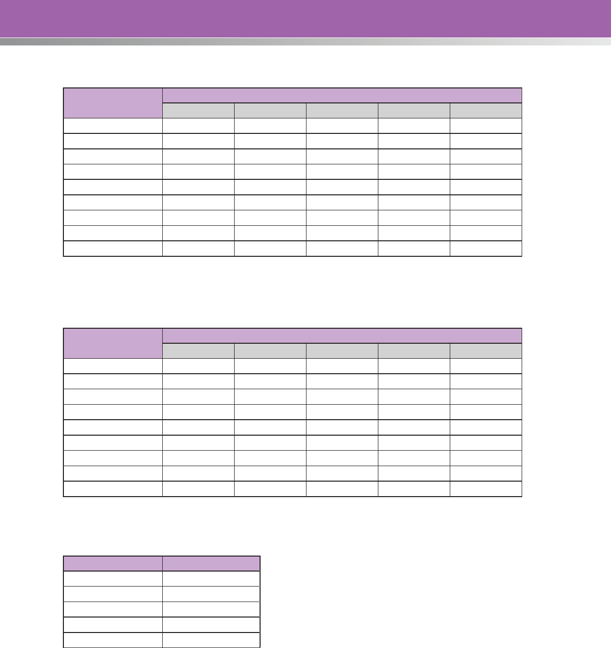
61
Probability of Crash Severity for Vehicle-Pedestrian/Cyclist Crashes
Speed Limit (mph)
Crash Severity
K A B C O
20 0.0028 0.0339 0.2053 0.5631 0.1949
25 0.0040 0.0435 0.2335 0.5555 0.1635
30 0.0057 0.0549 0.2622 0.5415 0.1357
35 0.0080 0.0684 0.2905 0.5219 0.1112
40 0.0110 0.0841 0.3178 0.4970 0.0901
45 0.0150 0.1020 0.3432 0.4677 0.0721
50 0.0202 0.1221 0.3657 0.4349 0.0571
55 0.0268 0.1443 0.3846 0.3997 0.0446
60 0.0351 0.1682 0.3993 0.3630 0.0344
Probability of Crash Severity for Vehicle-Pedestrian/Cyclist Crashes
Speed Limit (mph)
Crash Severity
K A B C O
20 0.002 0.0006 0.0081 0.0862 0.9049
25 0.0004 0.0009 0.0116 0.1081 0.879
30 0.0006 0.0015 0.0158 0.1313 0.8508
35 0.001 0.0022 0.0218 0.1591 0.8159
40 0.0016 0.0031 0.0289 0.187 0.7794
45 0.0025 0.0044 0.0386 0.2188 0.7357
50 0.0037 0.0062 0.0495 0.2491 0.6915
55 0.0055 0.0088 0.0635 0.2816 0.6406
60 0.008 0.0117 0.0788 0.3105 0.591
The City of Palm Bay uses the societal costs of crashes shown below:
Crash Severity Societal Cost ($)
K 3,366,388
A 233,100
B 46,620
C 24,510
O 2,590
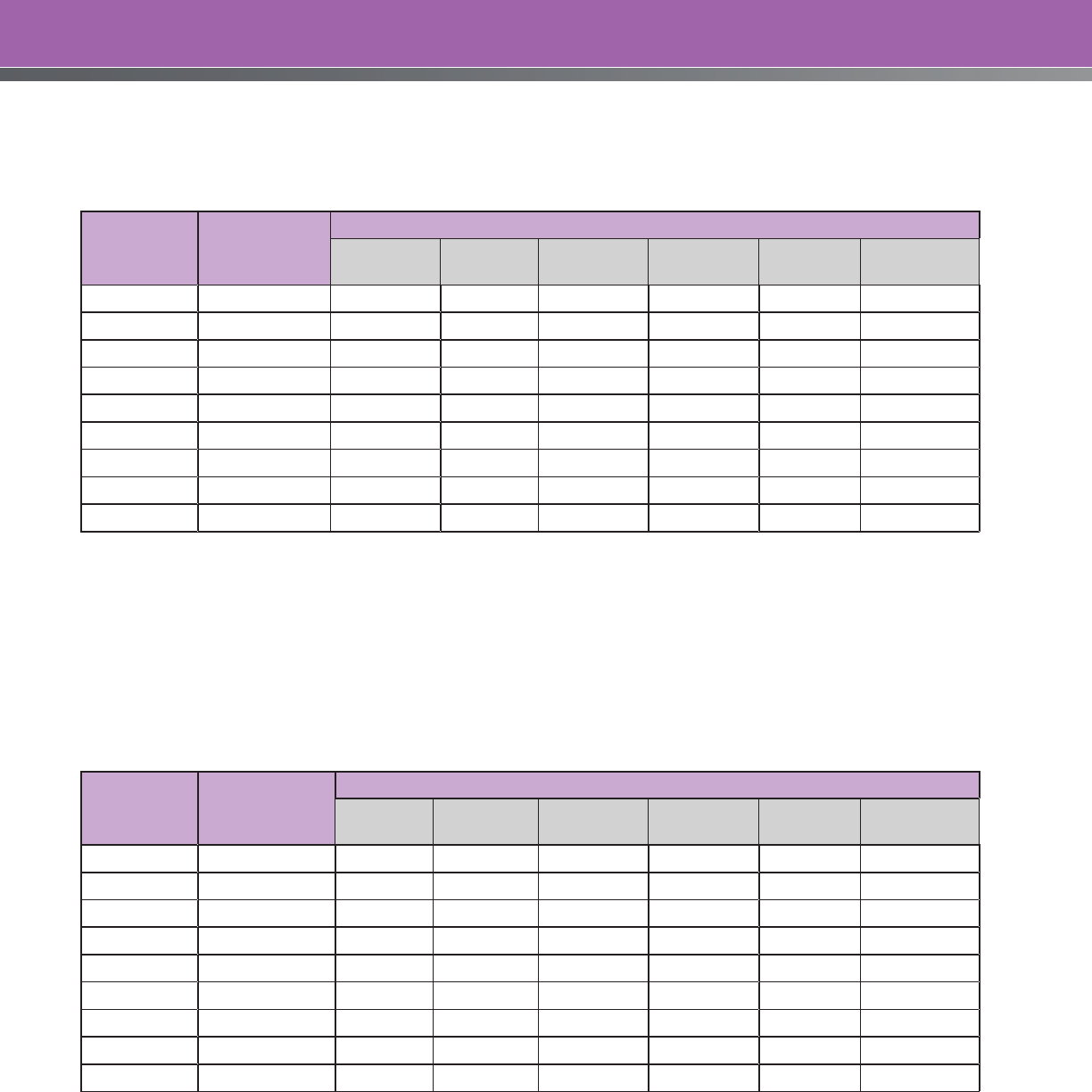
62
Therefore, employing the crash model for vehicle-pedestrian/cyclist, the probability distributions for the
different crash severities, and the societal costs for the different crash severities, the cost of vehicle-
pedestrian/cyclist crashes for the different available speed limits is shown below.
Speed Limit
(mph)
No. of Ped/
Cyclist
Crashes
Crash Costs by Severity ($)
K A B C O Total
20 6.7 62,820 52,664 63,787 91,982 3,364 274,617
25 4.3 57,509 43,306 46,491 58,149 1,809 207,263
30 2.7 52,516 35,024 33,455 36,324 962 158,280
35 1.8 47,233 27,963 23,752 22,435 505 121,888
40 1.1 41,618 22,033 16,652 13,691 262 94,256
45 0.7 36,368 17,124 11,524 8,256 134 73,407
50 0.5 31,385 13,136 7,869 4,920 68 57,378
55 0.3 26,684 9,948 5,303 2,897 34 44,867
60 0.2 22,395 7,431 3,528 1,686 17 35,058
It is noted that under this particular crash model, the number of pedestrian and cyclist crashes
decreases as the speed limit increases. This is likely due to the fact that higher speed roads have lower
pedestrian and cyclist traffic than similar lower speed roads. In other words, exposure to these types of
crashes decreases as speed increases.
The same methodology is employed to identify the societal cost of vehicle-vehicle crashes for the
different speed limit alternatives.
Speed Limit
(mph)
No. of Vehicle-
Vehicle
Crashes
Crash Costs by Severity ($)
K A B C O Total
20 19.4 — 2,256 5,145 32,599 46,386 86,386
25 17.0 114,456 2,378 6,419 35,916 39,842 199,011
30 14.9 20,101 3,132 8,073 39,551 33,984 104,839
35 13.1 26,475 4,583 9,655 42,183 28,884 111,780
40 11.5 38,746 5,902 11,698 44,883 24,322 125,552
45 10.1 54,437 7,303 13,617 46,323 20,402 142,082
50 8.9 74,689 9,102 15,970 47,593 16,910 164,265
55 7.8 97,064 11,262 17,983 47,578 13,957 187,845
60 6.8 126,696 14,037 20,257 47,229 11,353 219,572
It is noted that the number of crashes decreases as the speed limit increases. This is likely due to the fact
that the design of higher speed roads affords more generous dimensions and greater safety features
than similar lower speed facilities.
63
The total crash costs are the sums of the vehicle-vehicle crash costs and the vehicle-pedestrian/cyclist
crash costs.
Speed Limit (mph)
Ped/Cyclist Crash
Costs ($)
Vehicle-Vehicle Crash
Costs ($) Total Crash Costs ($)
20 274,617 86,386 361,003
25 207,263 199,011 406,275
30 158,280 104,839 263,120
35 121,888 111,780 233,669
40 94,256 125,552 219,808
45 73,407 142,082 215,489
50 57,378 164,265 221,642
55 44,867 187,845 232,712
60 35,058 219,572 254,630
According to published data on the fuel efficiency of late model passenger cars and light trucks
according to speed, the annual fuel consumption for different speed limits can be calculated.
Assuming a cost for gas of $3.50/gallon yields an annual fuel cost. This annual fuel cost can be added
to the annual crash costs to determine the net societal cost for the different speed limit alternatives. The
results are shown below.
Speed Limit
(mph)
Fuel Economy
(mpg)
Annual Fuel
Annual Crash
Cost ($) Total Cost ($)Gallons
Fuel Cost
(at $3.50/gal)
20 26.4 292,553 1,023,936 361,003 1,384,939
25 30.2 255,848 895,467 406,275 1,301,741
30 31.8 243,161 851,063 263,120 1,114,183
35 32.7 236,190 826,664 233,669 1,060,332
40 32.6 236,733 828,564 219,808 1,048,372
45 32.8 235,559 824,457 215,489 1,039,946
50 32.1 240,698 842,443 221,642 1,064,086
55 31.1 248,441 869,542 232,712 1,102,254
60 29.0 266,095 931,332 254,630 1,185,961
Under an optimal speed limit approach to Eldron Boulevard, the recommended speed limit is 45 mph.
The subsequent analysis does not include the cost of travel time, or automobile emissions, which would
typically be included in the thorough analysis.

64
Safe Systems Approach
Under the safe systems approach to setting the speed limit, the critical factor is the type of crashes that
can be expected to occur given the physical features of the road, and the types of road users that are
expected to be encountered.
In this instance, pedestrians and cyclists are permitted to use Eldron Boulevard but cyclists are very
infrequent, and pedestrians walking along the road are provided with a sidewalk that is set back
from the edge of pavement. The fact is that pedestrian-vehicle and cyclist-vehicle interactions are
uncommon, and are not a significant factor in determining a “safe speed limit.”
However, there are 26 two-way, stop controlled intersections and 86 driveways (85 residential and one
minor commercial) along this section of Eldron Boulevard. This means that the potential for right-angle
crashes, which have the greatest potential for causing serious injury to vehicle occupants, is significant.
Therefore, under a safe systems approach to setting speed limits, speeds on Eldron Boulevard from
Jupiter Road to Raleigh Road should be limited to those speeds where a right-angle crash will not cause
any serious injuries. This being the case, research on human biomechanical tolerance, and vehicle
crashworthiness studies indicate that speeds should be limited to 30 mph.
The recommended speed limit under the safe systems approach is 30 mph.
The recommended speed limits yielded by each speed limit setting method, and the actual speed limit
enacted by the road authority are shown in Tables 15 and 16.
Table 15. Recommended Speed Limits for the Eldron Boulevard Case Study
Eldron Boulevard, Florida
Actual Speed Limit 40
Illinois DOT 40
Northwestern 45
USLIMITS2 40
Optimal Speed 45
Safe System Speed 30
65
CASE STUDY 2: Rural Arterial Road
Roadway improvements undertaken in an 11.5-mile segment of State Route 67 between Milepost 11.3
and 22.8 in California prompted the need for a re-examination of the existing 55 mph speed limit. This is
an existing road with consistent road and land use characteristics throughout.
State Route 67 is a 24.4-mile road running primarily in a north-south direction between the City of El
Cajon and the community of Ramona. The study segment is a 2-lane highway, which traverses hilly
terrain, resulting in undulating vertical grades and winding horizontal curves. Strategically-located
passing lanes are present through the study area.
Traffic volumes are as follows:
Milepost 2011 AADT
13.56 24,900
15.20 25,500
20.87 25,000
21.35 29,500
Average 25,350
The roadway is asphalt with varying shoulder widths throughout. Shoulders are generally paved and
range from 3 feet (1.0 meter) to 8 feet (2.4 meters).
A painted median is provided that includes a median rumble strip and raised pavement markers. The
median is typically three feet wide.
In addition to the appropriate traffic control devices and traffic barriers, 11 digital Speed Feedback
signs are employed.
There are three signalized intersections in the study area.
A Doppler radar system was used to conduct spot speed studies at five different locations within the
study area.
Milepost
85th Percentile
Speed (mph)
Median Speed
(mph)
Mean Speed
(mph)
Upper Limit of
the 10 mph
Pace (mph)
Percent
Exceeding the
55 mph
11.30 61 56 56 61 57
15.00 63 57 57 60 60
18.10 65 60 60 64 83
19.70 59 56 56 60 59
21.00 54 51 51 55 8
Average 60.4 56.0 56.0 60.0

66
Based on a review of the horizontal alignment in the study section, the design speed is 50 mph. None of
the curves require an advisory speed warning.
The 3-year crash rate for the entire study area is 0.80 crashes per million-vehicle-miles, which is lower
than the statewide average crash rate of 1.51 crashes per million-vehicle-miles. However, there have
been 17 fatal crashes in the 3-year analysis period that have been evenly distributed throughout the
study section. The fatal crash rate is 0.46 crashes per million-vehicle-miles (MVM), which is almost double
the statewide average fatal crash rate of 0.25 crashes/MVM.
Public and private accesses to State Route 67 were inventoried and consist of the following:
NBND (milepost) SBND (milepost)
Private Access 12.10
12.17
12.38
12.76
13.80
13.96
14.07
14.10
14.34
14.36
14.89
15.46
15.67
15.89
16.13
16.96
17.00
17.89
18.05
18.14
18.21
20.25
11.49
11.96
12.78
13.69
13.78
14.06
14.89
15.56
16.19
16.28
16.45
17.43
17.51
18.16
18.27
18.37
18.54
18.92
Public Road 14.35 (Iron Mountain Trail)
17.73 (Rockhouse Road)
20.87 (Mussey Grade Road)
13.56 (Scripps Poway Parkway)
15.15 (Poway Road)
18.11 (Mount Woodson Road)
18.55 (Archie Moore Road)

67
All of the private accesses are to single family residential dwellings or small-scale agricultural operations.
State Route 67 has a rural cross-section, so there are no sidewalks. Pedestrians and cyclists are not
prohibited from the facility, but the volume of both user groups is extremely low.
Parking is permitted, but there are no significant roadside attractions, so parking activity is negligible.
Five test runs were undertaken during off-peak periods, and the average test run speed was 63 km/h.
Engineering Method Using Operating Speed
Using the Illinois DOT Method
STEP 1: Establish the Prevailing Speed
The prevailing speed is the average of the 85th percentile speed, the upper limit of the 10 mph pace,
and the average test run speed, rounded to the nearest 5 mph increment.
A B C (A+B+C)/3
Milepost
85th Percentile
Speed (mph)
Upper Limit of
the 10 mph
Pace (mph)
Avg. Test Run
Speed (mph)
Prevailing
Speed Rounded
11.30 61 61 63 62 60
15.00 63 60 63 62 60
18.10 65 64 63 64 65
19.70 59 60 63 61 60
21.00 54 55 63 57 55
STEP 2: Supplementary Investigations (Optional)
Adjustment factors for determining the proposed posted speed limit may be determined by further
investigation of any or all of the following four conditions:
• Elevated Crash Risk: The speed zone being studied has a crash rate that is lower than the
statewide average for similar facilities. However, it is still deemed a high-crash segment based on
the elevated fatal crash rate, which is double the statewide average. Therefore, a 10 percent
reduction in the prevailing speed is appropriate.
• Access Control: The access conflict number (ACN) is calculated for the speed zone, based on 40
private accesses to residential driveways and farms, and 7 public road intersections.
68
ACN* Reduction (%)
< 40 0
41 to 60 5
> 60 10
Therefore, no adjustment is required for access concerns.
• Pedestrian Activity: There is no significant pedestrian activity, so no further adjustment is required
for this factor.
• Parking: Parking is negligible and is not a factor in determining the posted speed limit.
The total adjustment from the 4 different factors is 10 percent.
Step 3: Selection of Preliminary Speed Limit
The preliminary speed limit is either the calculated prevailing speed (from Step 1), or if the optional
investigation was undertaken, it is the prevailing speed as adjusted by application of the percentage
corrections from the optional investigation (Step 2).
Milepost
Prevailing Speed
(Step 1), mph
Adjusted Speed
(Step 2), mph
Preliminary Speed Limit
(Rounded), mph
11.30 60 54 55
15.00 60 54 55
18.10 65 59 60
19.70 60 54 55
21.00 55 50 50
The following rules apply to the outcome:
• The preliminary posted speed limit should be the closest 5 mph increment to the (adjusted)
prevailing speed.
• The preliminary posted speed limit shall not differ from the prevailing speed (from Step 1) by more
than 9 mph or by more than 20 percent, whichever is less.
Both of these conditions are satisfied by the preliminary speed limits reported above.
69
Step 4: Violation Check
The proposed speed limit should be either the preliminary posted speed limit or the 50th percentile
speed, whichever is greater. In all cases, the preliminary speed limit and the median speeds yield the
same speed limit (rounded to the nearest 5 mph increment).
Milepost Preliminary, mph Median, mph
11.30 55 56
15.00 55 57
18.10 60 60
19.70 55 56
21.00 50 51
If the proposed speed limit exceeds the statutory speed limit for the highway in question, either the
statutory speed or the proposed speed limit may be posted. If the selected speed limit results in a
violation rate greater than 50 percent, the appropriate police agency(ies) should be notified that extra
enforcement efforts may be necessary.
It is noted that differences in posted speeds between adjacent speed zones should not be more than
10 mph. However, the Illinois policy permits a larger difference provided that adequate speed reduction
signs are posted.
Using the Northwestern Speed Zoning Technique
Milepost
85th Percentile Speed
(mph) (km/h)
Upper Limit of the
10 mph Pace (mph)
(km/h)
Average Test Run Speed
(mph) (km/h)
11.30 61 (98) 61 (98) 63 (101)
15.00 63 (101) 60 (97) 63 (101)
18.10 65 (105) 64 (103) 63 (101)
19.70 59 (95) 60 (97) 63 (101)
21.00 54 (87) 55 (88) 63 (101)
For the minimum speed study, the speed measurements yield the following:
Justified from Table 13
Milepost
85th Percentile
Speed (mph)
(km/h)
Upper Limit of
the 10 mph Pace
(mph) (km/h)
Average Test Run
Speed (mph)
(km/h)
Weighted Limit
(mph) (km/h)
Speed Limit
(Rounded), mph
(km/h)
11.30 60 (100) 65 (110) 65 (110) 635 (1070) 65 (110)
15.00 60 (100) 65 (110) 65 (110) 635 (1070) 65 (110)
18.10 65 (110) 65 (110) 65 (110) 650 (1100) 65 (110)
19.70 55 (90) 65 (110) 65 (110) 620 (1040) 60 (100)
21.00 55 (90) 60 (100) 65 (110) 605 (1010) 60 (100)
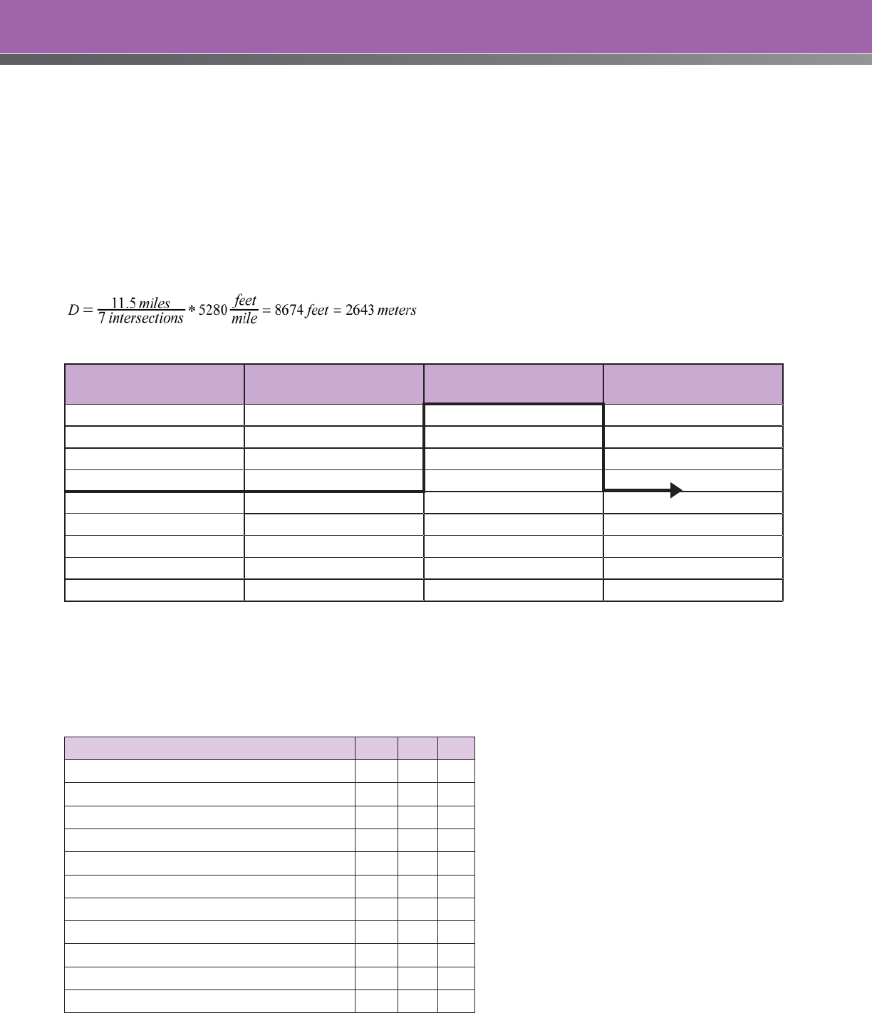
70
The recommended speed limit based on the minimum study is 60 to 65 mph depending on the location
within the study area. The lower speeds being produced at the higher mileposts may cause the analyst
to review the site and traffic conditions to determine if the speed zone should be divided into two
separate zones. The conditions are consistent through the study area, and the difference in the speed
limit recommended by the minimum study is only 5 mph. Therefore, the study area will be considered as
one speed zone.
The speed limit from the minimum study needs to be checked against the major physical features of the
road. The design speed of State Route 67 is 50 mph (80 km/h), and the length of the road under study is
11.5 miles (18.5 kms). The average distance between intersections is:
Design
Speed (km/h)
Average Distance
Between Intersections (m)
Length of Proposed
Zone (km)
Maximum Speed Limit
(km/h)
110 400 1.5 110
100 300 1.0 100
90 250 0.8 90
90 175 0.7 80
70 125 0.6 70
70 100 0.5 60
50 75 0.4 50
50 60 0.3 40
30 45 0.2 30
All three criteria are satisfied with the 70 km/h speed limit. Therefore, the minimum study recommends a
speed limit of 45 mph (70 km/h).
Continuing on with the detailed analysis, the factors determined from the various tables are:
Adjustment Factors
Non-commercial Access (Table 20) -5
Commercial Access (Table 20) +5
Lane Width (Table 21) +5
Functional Classification (Table 22) -5
Median Type (Table 23) 0
Shoulder Type and Width (Table 24) 0
Pedestrian Activity (Table 25) -15
Parking Activity (Table 26) 0
Roadway Alignment (Table 27) +10
Crash Rate (Table 28) +10
Totals +30 -25 =+5

71
The overall adjustment factor (OAF) is +30 which can be used to determine the multiplication factor
(MF) as:
MF = (100+OAF)/100 = (100+30)/100 = 1.30
The multiplication factor is greater than the maximum allowed, so it is reduced to 1.25. Therefore, the
recommended speed limit (SL) is the speed limit from the minimum study multiplied by the multiplication
factor and rounded to the nearest 10 km/h:
SL = 70 km/h * 1.25 = 87.5 km/h ➞ 90 km/h or 55 mph
The recommended speed limit based on the Northwestern Speed Zoning method is 55 mph.
Expert System (USLIMITS2)
The data from the State Route 67 speed limit study was entered into the USLIMITS2 program to determine
the recommended speed limit for this section of road. The entered data and the recommended speed
limit are shown in the boxed area below. The recommended speed limit is 55 mph.
The speed data at Mileposts 18.10 and 21.00, if entered into USLIMITS2 using the same traffic and
geometric data as above, will produce recommended speed limits of 60 mph and 50 mph,
respectively. These are only 5 mph different from the other mileposts, and it is desirable to use a
consistent 55 mph throughout the study area to encourage speed limit compliance.
Optimal Speed Limit
The optimal speed limit is determined by calculating and selecting the speed that produces the
lowest societal cost. In this case study, only crash and fuel costs will be considered, to demonstrate
the method. In a full analysis, other societal costs would be analyzed, including time travel costs,
automobile emissions, etc.
Step 1: Calculate the Crash Costs
The road authority has developed the following crash prediction models using regression techniques
and traffic, infrastructure, and historic crash data for roads under its control:
()
ADTXSLEXPLN
0000015.000045.00102.0000016.0 +++∗
=
Where: N = Number of crashes per year, per mile
SL = Posted Speed Limit (mph)
X = Number of intersections on the segment
ADT = Average daily traffic
L = Length (miles)
Additionally, the road authority has examined the severity distributions of the two crash types based on
speed, and has produced the following probabilities using the KABCO severity scale. The KABCO severity
scale was developed by the National Safety Council, and is used by investigating officers to classify injury
severity for occupants into one of five categories: K – killed; A – disabling injury; B – evident injury; C –
possible injury; O – no apparent injury. These definitions may vary slightly for different police agencies.

72
USLIMITS2 Data Output
Top of Form
Basic Project Information
Project Name – Case Study 2
Project Number –
Project Date – 09-21-2011
State – California
County – San Diego County
City –
Route – State Route 67
Route Type – Road Section in Undeveloped
Area
Termini from – Milepost 11.3
Termini to – Milepost 22.8
Route Status – EXISTING
Description – FHWA/ITE Informational Report
Case Study
Roadway Information
85th Percentile Speed – 61 mph
50th Percentile Speed – 56 mph
Section Length – 11.50 mile(s)
Statutory Speed Limit – 55 mile(s)
AADT – 23500
Adverse Alignment – No
Lanes and Presence/Type of Median – Two-lane
road or undivided multi-lane
Number of Lanes – 2
Roadside Hazard Rating – 3
Crash Data Information
Crash Data Months/Years – 3.00
Crash AADT – 25000
Total Number of Crashes – 252
Total Number of Injury Crashes – 145
Section Crash Rate – 80
Section Injury Rate – 46
Crash Rate Average for Similar Sections – 151
Injury Rate Average for Similar Sections – 25
Comments –
Recommended Speed Limit is: 55
The crash rate of the section is 80 per 100
MVMT. The average rate for similar sections is
151 per 100 MVMT, and the critical rate is 169
per 100 MVMT. The crash rate of this section
is 47 percent lower than the average crash
rate for similar sections. The rate of injury
crashes for the section is 46 per 100 MVMT.
The average rate for similar sections is 25
per 100 MVMT, and the critical rate is 32 per
100 MVMT. The rate of injury crashes for this
section is 84 percent higher than the average
rate for similar sections. A comprehensive
crash study should be undertaken to identify
engineering and traffic control deficiencies
and appropriate corrective actions. The
speed limit should only be reduced as a
last measure after all other treatments have
either been tried or ruled out.
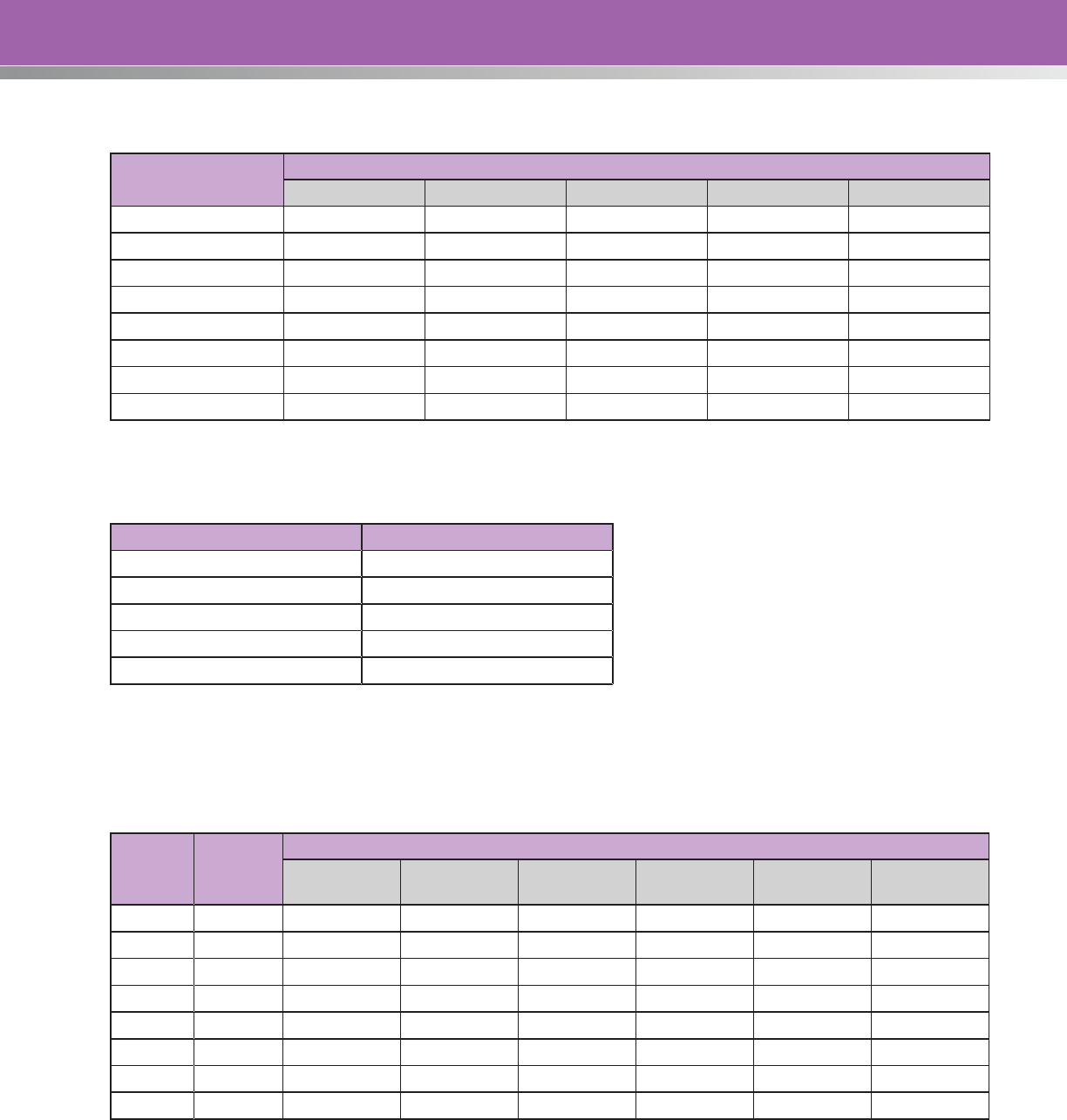
73
Probability of Crash Severity for Different Speeds
Speed Limit (mph)
Crash Severity
K A B C O
40 0.0016 0.0031 0.0289 0.187 0.7794
45 0.0025 0.0044 0.0386 0.2188 0.7357
50 0.0037 0.0062 0.0495 0.2491 0.6915
55 0.0055 0.0088 0.0635 0.2816 0.6406
60 0.0080 0.0117 0.0788 0.3105 0.5910
65 0.0116 0.0160 0.1001 0.3390 0.5333
70 0.0200 0.1250 0.3651 0.4349 0.0550
75 0.0350 0.1500 0.3846 0.4010 0.0294
The road authority uses the societal costs of crashes shown below:
Crash Severity Societal Cost ($)
K 3,366,388
A 233,100
B 46,620
C 24,510
O 2,590
Therefore, by employing the crash model, the probability distributions for the different crash severities,
and the societal costs for the different crash severities, the cost of crashes for the different available
speed limits is shown below.
Speed
Limit
(mph)
No. of
Crashes
Crash Costs by Severity ($)
K A B C O Total
40 18.1 97,627 13,098 24,421 83,075 36,589 254,810
45 19.1 160,524 19,563 34,324 102,288 36,344 353,044
50 20.1 250,006 29,008 46,319 122,547 35,948 483,829
55 21.1 391,076 43,327 62,529 145,784 35,045 677,760
60 22.2 598,601 60,619 81,655 169,156 34,023 944,054
65 23.4 913,386 87,236 109,154 194,346 32,308 1,336,429
70 24.6 1,657,202 717,189 418,953 262,370 3,506 3,059,219
75 25.9 3,051,845 905,657 464,421 254,576 1,972 4,678,471
It is noted that the number of crashes increases as the speed limit increases. This is as expected.
According to published data on the fuel efficiency of late model passenger cars and light trucks
according to speed, the annual fuel consumption for different speed limits can be calculated. An

74
annual fuel cost can be calculated assuming a gasoline cost of $3.50/gallon. This annual fuel cost can
be added to the annual crash costs to determine the net societal cost for the different speed limit
alternatives. The results are shown below.
Speed Limit
(mph)
Fuel Economy
(mpg)
Annual Fuel
Annual
Crash Cost ($) Total Cost ($)Gallons
Fuel Cost
(at $3.50/gal)
40 28.6 3,448,995 1,2071,482 254,810 12,326,291
45 29.2 3,378,125 11,823,438 353,044 12,176,481
50 30.9 3,192,273 11,172,957 483,829 11,656,786
55 31.1 3,173,020 11,105,569 677,760 11,783,329
60 29.0 3,398,493 11,894,724 944,054 12,838,778
65 26.5 3,720,556 13,021,947 1,336,429 14,358,376
70 24.1 4,090,876 14,318,066 3,059,219 17,377,286
75 21.8 4,524,828 15,836,898 4,678,471 20,515,369
Under an optimal speed limit approach to State Route 67, the recommended speed limit is 50 mph.
The preceding analysis does not include the cost of travel time or automobile emissions, which would
typically be included in the thorough analysis and may affect the outcome of the analysis.
Safe Systems Approach
Under the safe systems approach to setting the speed limit, the critical factor is the type of crashes
that can be expected to occur given the physical features of the road, and the types of road users
that are expected to be encountered. Pedestrian and cyclists, while permitted on State Route 67, are
infrequent. Pedestrian-vehicle and cyclist-vehicle conflicts are rare, and do not factor into setting a
speed limit using the safe systems approach.
The controlling criteria in this instance are the presence of at-grade intersections and driveways
(which permit right-angle crashes), and the undivided cross-section (which permits head-on crashes).
State Route 67 has several at-grade intersections that are two-way stop controlled. The volumes on
these intersections are generally low and do not result in a significant right-angle crash risk because
of extremely low exposure. This being the case, the most significant crash type is the head-on crash.
Therefore, the appropriate speed limit under a safe system approach is about 50 mph (80 km/h).
The recommended speed limits yielded by each speed limit setting method and the actual speed limit
enacted by the road authority for State Route 67 are shown in Table 16.
Table 16. Recommended Speed Limits for the State Route 67 Case Study
State Route 67, California
Actual Speed Limit 55
Illinois DOT 55
Northwestern 55
USLIMITS2 55
Optimal Speed 50
Safe System Speed 50

75
SUMMARY OF RESULTS
Table 17 shows the recommended speed limits yielded by each speed limit setting method and the
actual speed limit enacted by the road authority for both case studies are shown below.
Table 17. Recommended Speed Limits for the Case Studies
Eldron Boulevard, Florida State Route 67, California
Actual Speed Limit 40 55
Illinois DOT 40 55
Northwestern 45 55
USLIMITS2 40 55
Optimal Speed 45 50
Safe System Speed 30 50
With the exception of the safe systems approach, the recommended speed limit from each of the
methodologies used are within 5 mph of each other. On the one hand, this suggests an inter-method
consistency that is reassuring. However, it needs to be remembered that these are only two specific
examples, and this consistency may not endure in other cases. In fact, the optimal speed and the
safe systems approaches are known to produce results that have a more pronounced difference from
the other methods in certain situations. This is perhaps not surprising since the Illinois DOT method, the
Northwestern method, and USLIMITS2 all start from the 85th percentile speed.
As expected, the safe speed approach resulted in speed limits that are at the low end of the range.
This becomes very apparent in the urban case on Eldron Avenue, where the potential for more frequent
right-angle crashes requires a more dramatic decrease in operating speeds to be consistent with the
zero tolerance for injury-producing crashes.

76
REFERENCES
1. Library of Congress, “Who Invented the Automobile?” http://www.loc.gov/rr/scitech/mysteries/auto.html (July 24, 2011).
2. Transport Research Centre, “Speed Management,” Joint Organisation for Economic Cooperation Development and European
Conference of Ministers of Transport, ITRD Number E130442 (Paris, France: 2006).
3. National Forum on Speeding Summary Report Strategies for Reducing Speeding-Related Fatalities and Injuries,
http://www.nhtsa.dot.gov/people/injury/enforce/ NatForumSpeeding/images/SpeedingForum.pdf.
4. Locomotive Act 1861, http://www.legislation.gov.uk/ukpga/Vict/24-25/70/section/11/enacted (August 26, 2011).
5. Department of Transport, “A Brief History of Registration,” Driver and Vehicle Licensing Agency
http://www.direct.gov.uk/prod_consum_dg/groups/dg_digitalassets/@dg/@en/@motor/documents/digitalasset/dg_180212.pdf
(September 6, 2011).
6. European Transport Safety Council news release, “Polish Presidency of the EU: Time to Start Work towards the 2020 Road
Safety Target,” http://www.etsc.eu/documents/copy_of_ETSC_Polish_Presidency_Press.pdf (July 4, 2011).
7. R. Elvik, P. Christensen, and A. Amundsen, “Speed and Road Accidents: An Evaluation of the Power Model,” The Institute of
Transport Economics (TOI), TOI Report 740/2004 (December 2004).
8. S.B. White and A. C. Nelson, “Some Effects of Measurement Errors in Estimating Involvement Rate as a Function of
Deviation from Mean Traffic Speed,”
Journal of Safety Research
, 2 (1970): 67–72.
9. E. Hauer, “Speed and Crash Risk: An Opinion,” (unpublished manuscript dated September 8, 2003, University of Toronto,
Department of Civil Engineering, Toronto, Ontario, Canada).
10. G.A. Davis, “Is the Claim that ’Variance Kills’ an Ecological Fallacy?” (paper 01-0530 from the Transportation Research
Board of the National Academies Annual Meeting, Washington DC (available on CD-Rom)).
11. Transportation Research Board of the National Academies (TRB), “Managing Speed: Review of Current Practice for Setting
and Enforcing Speed Limits,”
TRB Special Report 254
, National Research Council (Washington, DC: 1998).
12. National Committee on Uniform Traffic Laws and Ordinances.
Uniform Vehicle Code
Millennium Edition.
(Evanston, Illinois: 2000).
13. Y. Yang., “Optimal Speed Limit for Shared-Use Roadways,” (Doctoral diss., New Jersey Institute of Technology, July 2005).
14. Speed Limits New Zealand,
Guidelines for Setting Speed Limits and Procedures for Calculating Speed Limits.
15. Federal Highway Administration,
Manual on Uniform Traffic Control Devices for Streets and Highways
, 2009 Edition
http://mutcd.fhwa.dot.gov.
16. K. Fitzpatrick, P. Carlson, M.A. Brewer, M.D. Wooldridge, and S.P. Miaou,
Design Speed, Operating Speed and Posted
Speed Practices
, Transportation Research Board of the National Academies, National Cooperative Highway Research
Program Report 504 (Washington, DC: 2003).
17. Institute of Transportation Engineers,
Survey of Speed Zoning Practices
, An Informational Report (Washington, DC: 2001).
18. Commonwealth of Massachusetts, Massachusetts Highway Department,
Procedures for Speed Zoning on State and
Municipal Roadways
(2005).

77
19. Texas Department of Transportation,
Procedures for Establishing Speed Zones
(November 2006).
20. Maine Department of Transportation, “How Are Speed Limits Set?” http://www.maine.gov/mdot/community-programs/csd/
howlimit.php (July 13, 2011).
21. Illinois Department of Transportation, “Policy on Establishing and Posting Speed Limits on the State Highway System”
(March 2011).
22. Transportation Association of Canada,
Canadian Guidelines for Establishing Posted Speed Limits
(2009).
23. National Cooperative Highway Research Program for the Transportation Research Board of the National Academies,
An Expert System for Recommending Speed Limits in Speed Zones
, Research Results Digest 318 (May 2007).
24. J.G. Bared, P. Edara, and T. Kim, “Safety Impact of Interchange Spacing on Urban Freeways,” (paper presented at the 2006
Annual Meeting of the Transportation Research Board of the National Academies (January 2006).
25. C.V. Zegeer, J. Hummer, D. Reinfurt, L. Herf, and W. Hunter,
Safety Effects of Cross-Section Design for Two-Lane Roads
,
Volume I-Final Report, FHWA-RD-87/008 (October 1987).
26. Federal Highway Administration, Office of Operations,
Benefits of Access Management
brochure, FHWA-OP-03-066
http://ops.fhwa.dot.gov/access_mgmt/docs/benefits_am_trifold.htm.
27. R. Elvik, “Optimal Speed Limits: The Limits of Optimality Models,”
Transportation Research Record 1818
(2002): 32-38.
28. J. Langford, “Setting Speed Limits for a Safe System,” Monash University Accident Research Centre
http://www.austroads.com.au/pdf/TestMethod2/9._Setting_speed_limits__16_Nov_06_.pdf (August 12, 2011).
29. Ohio Department of Transportation.
Traffic Engineering Manual
, Part 12, Zones and Studies (Revised July 18, 2008).
30. Florida Department of Transportation,
Speed Zoning for Highways, Roads, and Streets in Florida
, Manual Number
750-010-002, 2010 Edition.
31. Alaska Department of Transportation and Public Facilities,
Establishment of Speed Limits and Zones, Policy and Procedure
Manual
(June 2000).
32. Roads and Traffic Authority NSW, NSW Speed Zoning Guidelines, Version 3.0, Safer Roads Branch (2009).
33. Federal Highway Administration,
Standard Highway Signs
, 2004 Edition
http://mutcd.fhwa.dot.gov/ser-shs_millennium_eng.htm.
34. Washington Department of Transportation,
Traffic Manual
, Chapter 2, Signs (March 2002).
35. Montana Department of Transportation,
Montana Traffic Engineering Manual
, Chapter 40-Speed Studies (November 2007).
36. V.W. Inman, S. Miller, S. Tackett, J.A. Molino, and A.Z. Zineddin, “Exploration of Appropriate Intervals for Locating Speed
Limit Signs,” Transportation Research Board Annual Meeting CD-ROM (2008).
37. Alberta Transportation,
Driver (Speed) Feedback Signs
, Recommended Practice, Government of Alberta, Canada
(December 2010).
38. Institute of Transportation Engineers,
Methodologies for the Determination of Advisory Speeds
, Publication No. IR-132E
(Washington, DC: 2010).

78
39. K. Fitzpatrick, M. Brewer, K. Obeng-Boampong, E.S. Park, and N. Trout,
Speeds in School Zones
, Report No. FHWA/TX-
09/0-5470-1, Texas Transportation Institute, The Texas A&M University System (College Station, Texas: February 2009).
40. VicRoads, “School Speed Zones” http://www.vicroads.vic.gov.au/Home/SafetyAndRules/SafetyIssues/Speed/
SchoolSpeedZones.htm (August 28, 2011).
41. Ontario Ministry of Transportation,
Ontario Traffic Manual – Book 5 – Regulatory Signs
, Toronto, Ontario, Canada.
42. National Highway Traffic Safety Administration,
Speed Enforcement Program Guidelines
, Report No. DOT HS 810 915
(March 2008).
43. Wisconsin Department of Transportation, Bureau of Highway Operations, Traffic Engineering Section,
Wisconsin Statewide
Speed Management Guidelines
, (Madison, Wisconsin: June 2009).
44. Institute of Transportation Engineers.
Manual of Transportation Engineering Studies
(Washington, DC: 2000).
45. National Motorists Association,
Speed Limits, NMA’s Model Speed Zoning Law
http://www.motorists.org/speedlimits/home/nmas-model-speed-zoning-law.
46. National Highway Traffic Safety Administration, National Center for Statistics and Analysis,
Traffic Safety Facts 2007,
Data: Speeding
, DOT-HS-810-998 (Washington, DC: 2009).
47. C.N. Kloeden, G. Ponte, and A.J. McLean,
Travelling Speed and the Risk of Crash Involvement on Rural Roads
. Australian
Transport Safety Bureau, CR 204 (Canberra, Australia: 2001).
48. National Highway Traffic Safety Administration and Federal Highway Administration,
Speed Enforcement Camera Systems
Operational Guidelines,
Report No. DOT HS 810 916 (March 2008).
49. Federal Highway Administration, Office of Safety,
Procedures for Setting Advisory Speeds on Curves
, FHWA Document
No. FHWA-SA-11-22 http://safety.fhwa.dot.gov/speedmgt/ref_mats/fhwasa1122.
50. G. Forbes,
Speed Reduction Techniques for Rural High-to-Low Speed Transitions
, National Cooperative Highway Research
Program, Synthesis Report 412, Transportation Research Board of the National Academies (2011).
51. A. Edgar, “Speed Zoning Based on the Road Environment,” ITE
2005 Annual Meeting and Exhibit Compendium of
Technical Papers
, Institute of Transportation Engineers (2005).
52. E. Hauer, “Speed and Safety,”
Transportation Research Record 2103
, Transportation Research Board of the National
Academies (2009): 10–17.

79
APPENDIX A: GLOSSARY
The following definitions are provided to aid in the understanding of setting speed limits. They may or
may not coincide with terms and definitions found in related State statutes.
10 mph Pace: The 10 mph pace is the 10 mph range encompassing the greatest percentage of all the
measured speeds in a spot speed study.
85th Percentile Speed: The 85th percentile speed is the speed at or below which 85 percent of the
free-flowing vehicles travel.
Advisory Speed: Advisory speeds warn drivers to proceed at a speed lower than the speed limit due to
geometrics, surface, sight distance, or other conditions.
Annual Average Daily Traffic: Commonly abbreviated as AADT, the total number of vehicles traversing
a point or facility in one year divided by 365.
Average Speed: The average (or mean) speed is the most common measure of central tendency.
Using data from a spot speed study, the average is calculated by summing all the measured speeds
and dividing by the sample size.
Design Speed: The design speed is a selected speed used to determine the various geometric design
features of the roadway.
Differential Speed Limit: A system that prescribes different maximum speed limits for different vehicle
types or user groups. This is usually applied as one maximum speed limit for light passenger vehicles, and
a lower maximum speed limit for trucks and heavy commercial vehicles.
Free-flow Speed: Free-flow speed is the speed a driver chooses when there are no influences from other
vehicles, conspicuous enforcement, or environmental factors; in other words, this is the speed the driver
finds comfortable based on the appearance of the road.
Injury Minimization Speed Limit: Also known as a speed limit for safe systems, it is a speed limit that
is set so that the forces experienced by the human body in the event of a crash will not exceed
biomechanical tolerances resulting in death or a severe personal injury.
Optimal Speed Limit: A speed limit that yields the minimum total cost to society, including vehicle
operating costs, crash costs, travel time costs, and other societal costs.
Rational Speed Limit: A speed limit that is based on a formal, analytical review of traffic flow, roadway
design, local development, and crash data. For existing roads, it uses the 85th percentile speed of
free-flowing vehicles operating under normal traffic, weather, and roadway conditions as the speed
limit, adjusted down by factors that can affect safety, such as road design features and roadside
development and are not readily apparent to the motorist. The analysis also considers crash history and
the influence of speed as a contributing factor. The 85th percentile speed is based on the premise that
the vast majority of drivers will select a speed that is reasonable, safe, and prudent for a given road.
Drivers who exceed the 90th percentile have a significantly higher risk of crashing.
Road Safety Audit: A formal safety performance examination of an existing or future road or
intersection by an independent audit team.

80
Speed Dispersion: The speed dispersion refers to the normal spread in vehicle speeds observed in a
study section.
Speed Limit, Absolute: An absolute speed limit is a numerical value, the exceeding of which is always
in violation of the law, regardless of the conditions or hazards involved.
Speed Limits, Environment: An environmental speed limit is a speed limit created for the purpose of
meeting federal air quality standards.
19
Speed Limit, Posted: The posted speed limit is the value conveyed to the motorist on a black-on-white
regulatory sign. Standard engineering practice is to post speed limits for freeways, arterials, and any
roadway or street where speed zoning has altered the limit from the statutory value.
Speed Limit, Prima Facie: A prima facie speed limit is one above which drivers are presumed to be
driving unlawfully. Nevertheless, if charged with a violation, drivers have the opportunity to demonstrate
in court that their speed was safe for conditions at the time and not in violation of the speed limit, even
though they may have exceeded the numerical limit.
Speed Limits, Statutory: Numerical speed limits specifically provided for under a State’s traffic codes
that apply to various classes or categories of roads (e.g., rural expressways, residential streets, primary
arterials, etc.). State laws may or may not require that these limits be posted.
15
Speed Zoning: Speed zoning is the process of performing and engineering a study and establishing a
reasonable and safe speed limit for a section of roadway where the statutory speed limits given in the
motor vehicle laws do not fit the road or traffic conditions at a specific location.
Speeding: The legal definition of speeding is exceeding the posted speed limit. In the road safety
community, speeding is defined as exceeding the posted speed limit or speed too fast for conditions.
Test Run: A speed test run is performed by driving through a study area (potential speed zone) at a
reasonable free-flow speed and collecting speed data, then using this data to confirm speed limits or
speed data collected from other vehicles in the study area.
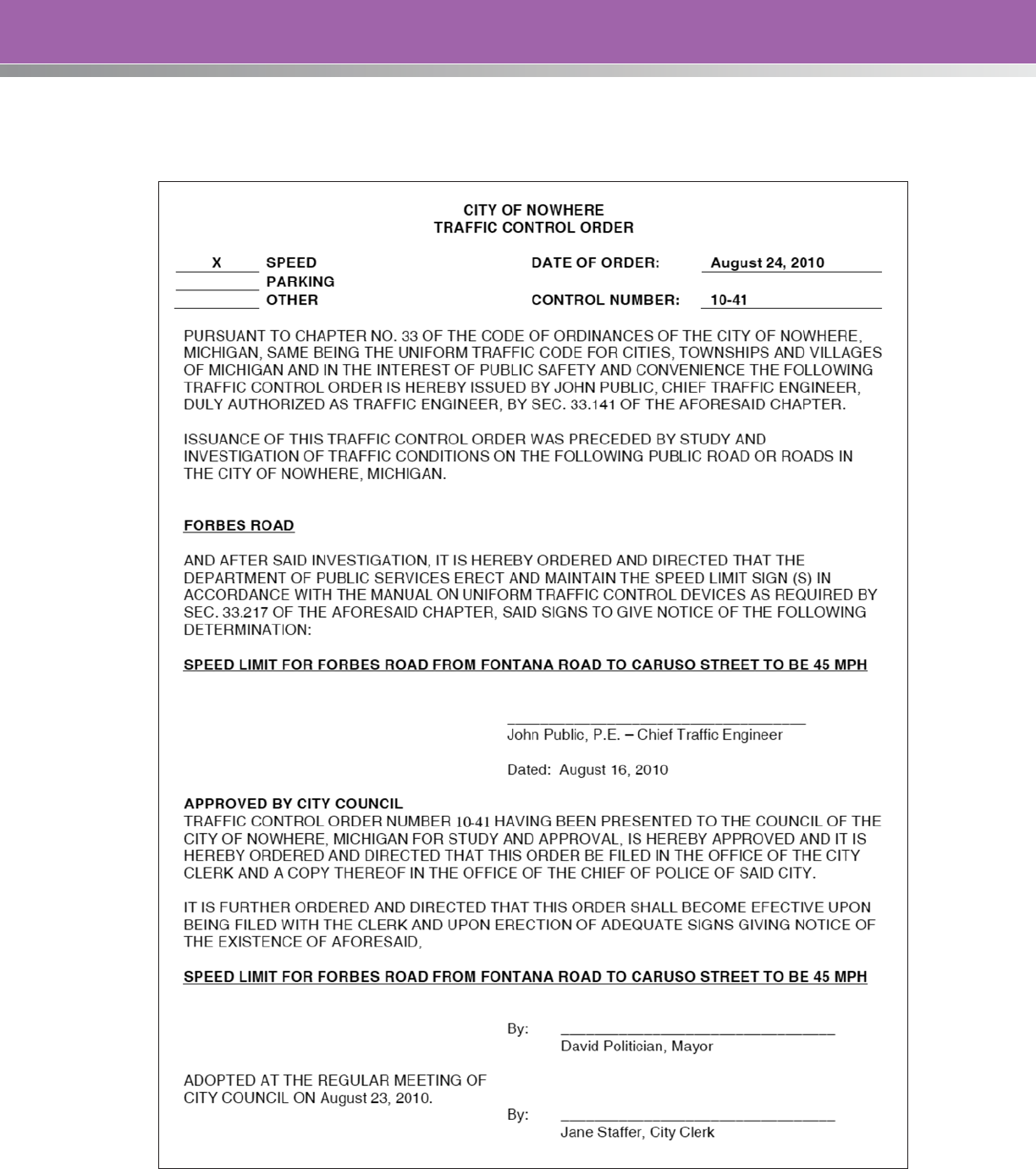
81
APPENDIX B: EXAMPLE TRAFFIC CONTROL ORDER
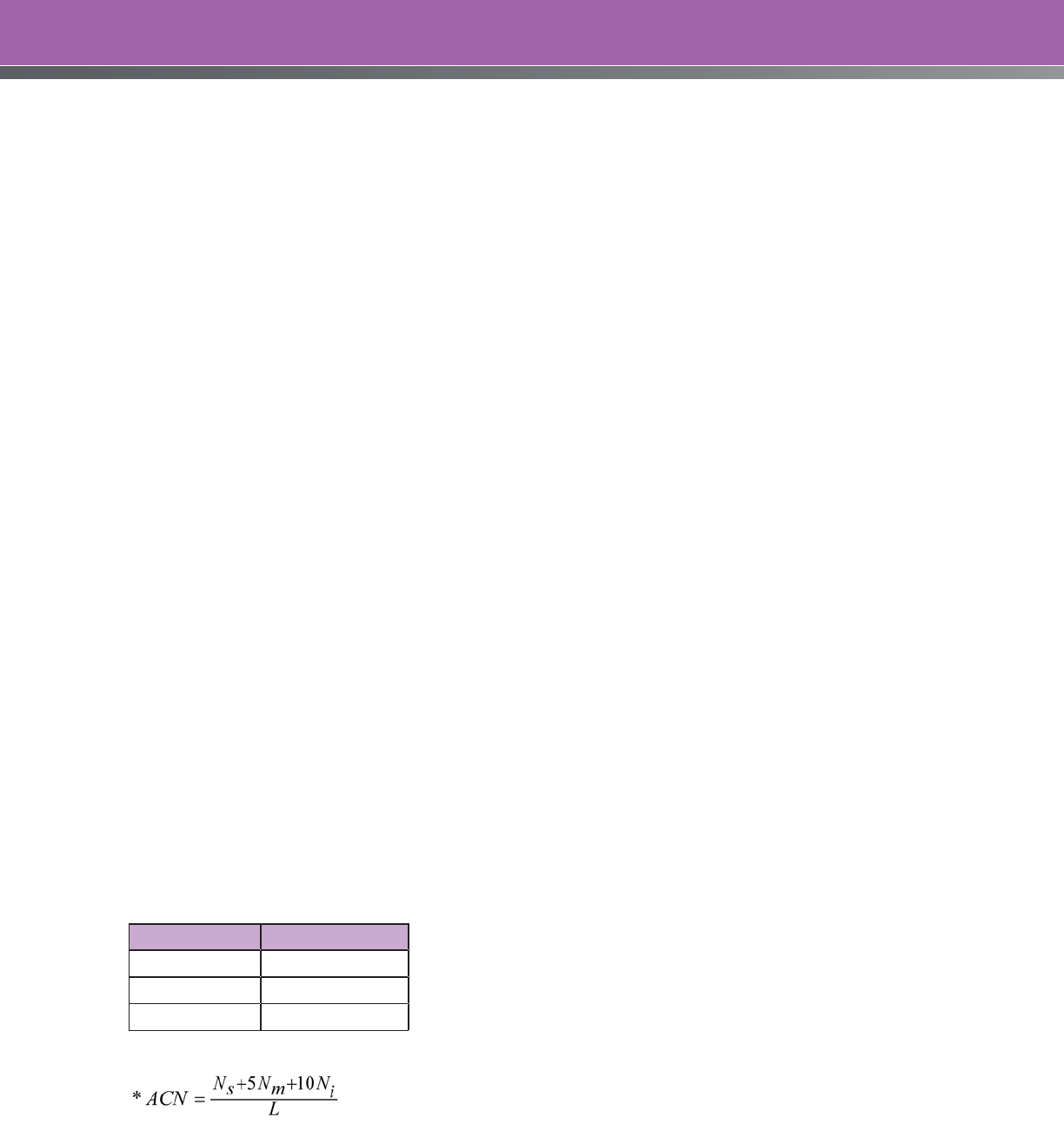
82
APPENDIX C: ILLINOIS POLICY ON SETTING SPEED LIMITS
(The material in this section is adapted from Policy on Establishing and Posting Speed Limits on the State Highway System,
published by the Illinois Department of Transportation (March 2011).)
Illinois statutes and the State Manual on Uniform Traffic Control Devices require that speed limits
other than statutory speed limits be based on “… an engineering study that has been performed in
accordance with traffic engineering practices. The engineering study shall include an analysis of the
current speed distribution of free-flowing vehicles.”
The following procedure shall be used to determine speed zones on streets and highways under the
jurisdiction of the DOT. The same procedure is recommended for local agencies.
STEP 1: Establish the Prevailing Speed
The prevailing speed is the average of the following three metrics, measured during free-flowing traffic conditions:
• 85th Percentile Speed: The speed at or below which 85 percent of the vehicles are traveling.
• Upper Limit of the 10 mph Pace: The 10 mph range containing the most vehicles.
• Average Test Run Speed: Determined on the basis of five vehicle runs in each direction over the
length of the proposed speed zone.
The prevailing speed is the nearest 5 mph increment to the average of the above three values.
STEP 2: Supplementary Investigations (Optional)
Adjustment factors for determining the proposed posted speed limit may be determined by further
investigation of any or all of the following four conditions:
• Elevated Crash Risk: If the speed zone being studied contains a portion of a high-crash segment
or contains a high-crash intersection as determined by the Bureau of Safety Engineering, the
prevailing speed may be reduced by 10 percent.
• Access Control: The access conflict number (ACN) is calculated for the speed zone, and this
number is used to determine the percent reduction of the prevailing speed as shown below.
ACN* Reduction (%)
< 40 0
41 to 60 5
> 60 10
Where:
N
s
= Number of field entrances and driveways to single-family dwellings
N
m
= Number of driveways to minor commercial entrances, multi-family residential units, and
minor street intersections
N
i
= Number of driveways to major commercial entrances, large multi-family developments,
and major street intersections

83
• Pedestrian Activity: Where no sidewalks are provided or where sidewalks are located immediately
behind the curb and the total pedestrian traffic exceeds 10 per hour for any 3 hours within any
8-hour period, the prevailing speed may be reduced by 5 percent. Pedestrians crossing the
route at intersections or established crossing points may be included if the point of crossing is not
controlled by a STOP or YIELD sign on the route in question, or does not have traffic signals.
• Parking: The prevailing speed may be reduced by 5 percent where parking is permitted adjacent
to the traffic lanes.
The adjustment factors from the four different factors are added together to produce a single
percentage adjustment that shall not exceed 20 percent.
Step 3: Selection of Preliminary Speed Limit
The preliminary speed limit is either the calculated prevailing speed (from Step 1), or if the optional
investigation was undertaken, it is the prevailing speed as adjusted by application of the percentage
corrections from the optional investigation (Step 2). The following rules apply to the outcome:
• The preliminary posted speed limit should be the closest 5 mph increment to the (adjusted)
prevailing speed.
• The preliminary posted speed limit shall not differ from the prevailing speed (from Step 1) by more
than 9 mph or by more than 20 percent, whichever is less.
Step 4: Violation Check
Using the spot speed data collected in Step 1, determine the median speed (the 50th percentile). The
proposed speed limit should be either the preliminary posted speed limit or the 50th percentile speed,
whichever is greater.
If the proposed speed limit exceeds the statutory speed limit for the highway in question, either the
statutory speed or the proposed speed limit may be posted. If the selected speed limit results in a
violation rate greater than 50 percent, the appropriate police agency(ies) should be notified that extra
enforcement efforts may be necessary.
It is noted that differences in posted speeds between adjacent speed zones should not be more than
10 mph. However, the Illinois policy permits a larger difference provided that adequate speed reduction
signs are posted.

84
APPENDIX D: NORTHWESTERN SPEED ZONING TECHNIQUE
The Northwestern Speed Zoning Technique is an example of an engineering method that can be used
to calculate a recommended speed limit for a particular facility. It is based on the 85th percentile
operating speed, and uses adjustments for different traffic, roadway, and performance characteristics.
The general sentiment in the Northwestern Speed Zoning Technique is that the 85th percentile speed
is a safe, self-selected speed that also provides a reasonable basis for enforcement. However, it must
be recognized that the driver selects a speed based on her/his evaluation of the perceived hazard,
and if there are hazards of which the driver is unaware, then the selected speed may be too high. The
commonly encountered hazards and the crash history of the road can be used to determine if the 85th
percentile speed is a suitable legislated speed limit.
The Northwestern Speed Zoning Technique provides adjustments for various features of the road—these
are generally applicable to most roads, but can be altered to suit local conditions and policies.
The procedure consists of two parts—a minimum study and a detailed analysis. The minimum study is
always carried out; the detailed analysis is undertaken when unusual road or land use characteristics
make the speed limit as determined by the minimum study seem inappropriate.
Minimum Speed Study
The data required for the minimum speed study are:
• Speed data:
» 85th percentile speeds
» Upper limit of the 15 km/h pace
» Average test run speed
• Physical Road data:
» Design speed
» Length of the proposed speed zone
» Average distance between intersections (not including alleys, driveways, or entrances unless
they are controlled by STOP signs or traffic signals).
The procedure used in the minimum speed study is to determine the speed limit based on the speed
data, subject to a maximum as determined by the physical features of the road.
The steps are as follows:
1. For each of the three speed measurements, use Table 18 to select the justified speed limit.
2. Compute a weighted average speed limit using the following weights, and round down to the
nearest 10 km/h:
• Justified speed limit from the 85th percentile speed: Weight = 3.

85
• Justified speed limit from the upper limit of the pace: Weight = 3.
• Justified speed limit from the average test run speed: Weight = 4.
10
433
85 runpace
SLSLSL
SL
++
=
Where: SL = Weighted average speed limit
SL
85
= Speed limit justified by the 85th percentile speed using Table 18
SL
pace
= Speed limit justified by the upper limit of the 15 km/h pace using Table 18
SL
run
= Speed limit justified by the average test run speed using Table 18
3. Using Table 19, select the highest speed limit that will satisfy all three conditions of design speed,
average distance between intersections, and length of the proposed speed zone.
4. The recommended speed limit is the lower of the weighted average (from Step 2) and the
maximum speed limit (from Step 3).
Table 18. Speed Limit Justified by Speed Data
85th Percentile Speed
(km/h)
Upper Limit of the 15
km/h Pace
Average Test Run Speed
(km/h)
Justified Speed Limit
(km/h)
< 34 < 33 < 30 30
34 – 44 33 – 42 30 – 38 40
45 – 54 43 – 52 39 – 48 50
55 – 64 53 – 62 49 – 56 60
65 – 74 63 – 72 57 – 65 70
75 – 84 73 – 80 66 – 75 80
85 – 94 81 – 88 76 – 85 90
95 – 104 89 – 96 86 – 94 100
> 104 > 96 > 94 110
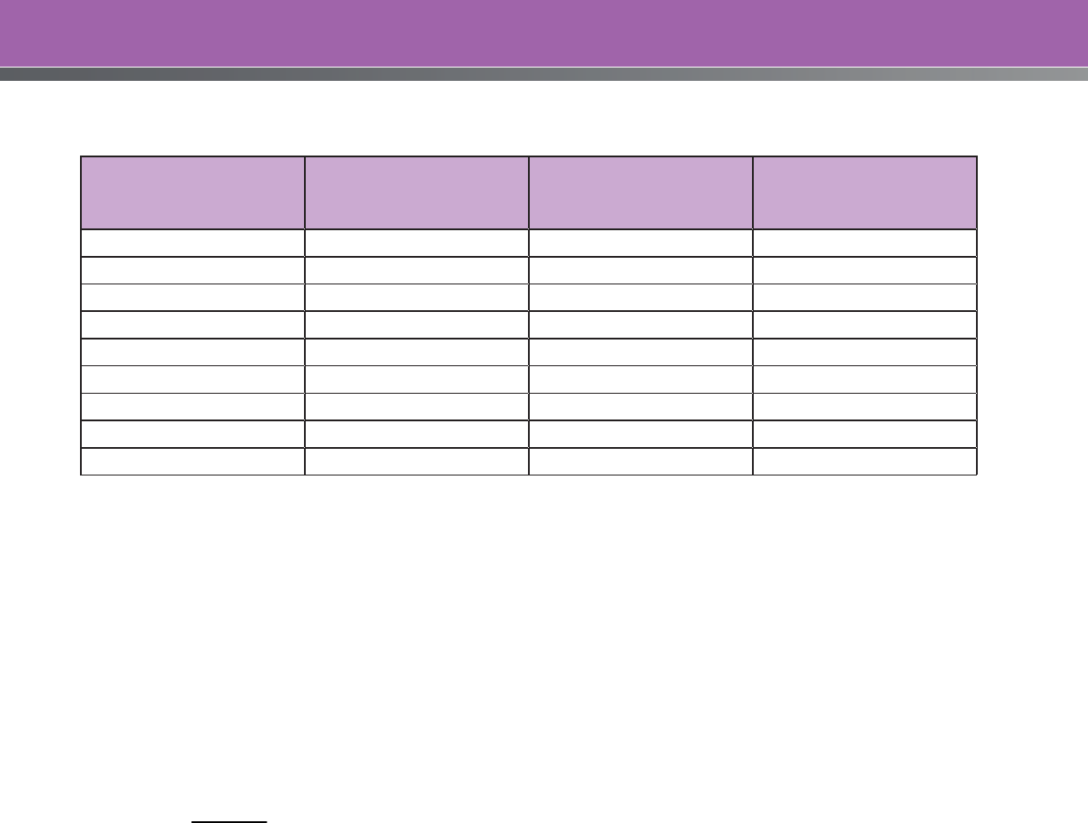
86
Table 19. Speed Limit Based on Road Parameters
Design Speed (km/h)
Average Distance
Between Intersections
(m)
Length of Proposed
Zone (km)
Maximum Speed Limit
(km/h)
110 400 1.5 110
100 300 1.0 100
90 250 0.8 90
90 175 0.7 80
70 125 0.6 70
70 100 0.5 60
50 75 0.4 50
50 60 0.3 40
30 45 0.2 30
Detailed Analysis
The data required for the minimum speed study are:
1. Using the recommended speed limit from the Minimum Speed Study and the other collected
data, consult Tables 3 to 11 and determine the adjustment factors based on additional traffic and
roadway features.
2. Add all of the adjustment factors together to obtain an overall adjustment factor.
3. Calculate the multiplier as follows:
100
100 OAF
MF
+
=
Where: MF = Multiplication Factor
OAF = Overall Adjustment Factor (from Step 2)
4. If the Multiplication Factor is greater than 1.25, set it to 1.25. If the Multiplication Factor is less than
0.75, set it to 0.75.
5. Multiply the recommended speed limit from the minimum speed study by the multiplication factor
and round to the nearest 10 km/h to produce the recommended speed limit.
Note: Table 20 will yield two adjustment factors—one for commercial, and one for non-commercial
driveways.
Also, if a detailed study is to be undertaken, then all of the information and tables must be included in
the analysis. It is not good practice to include selected items and ignore others.
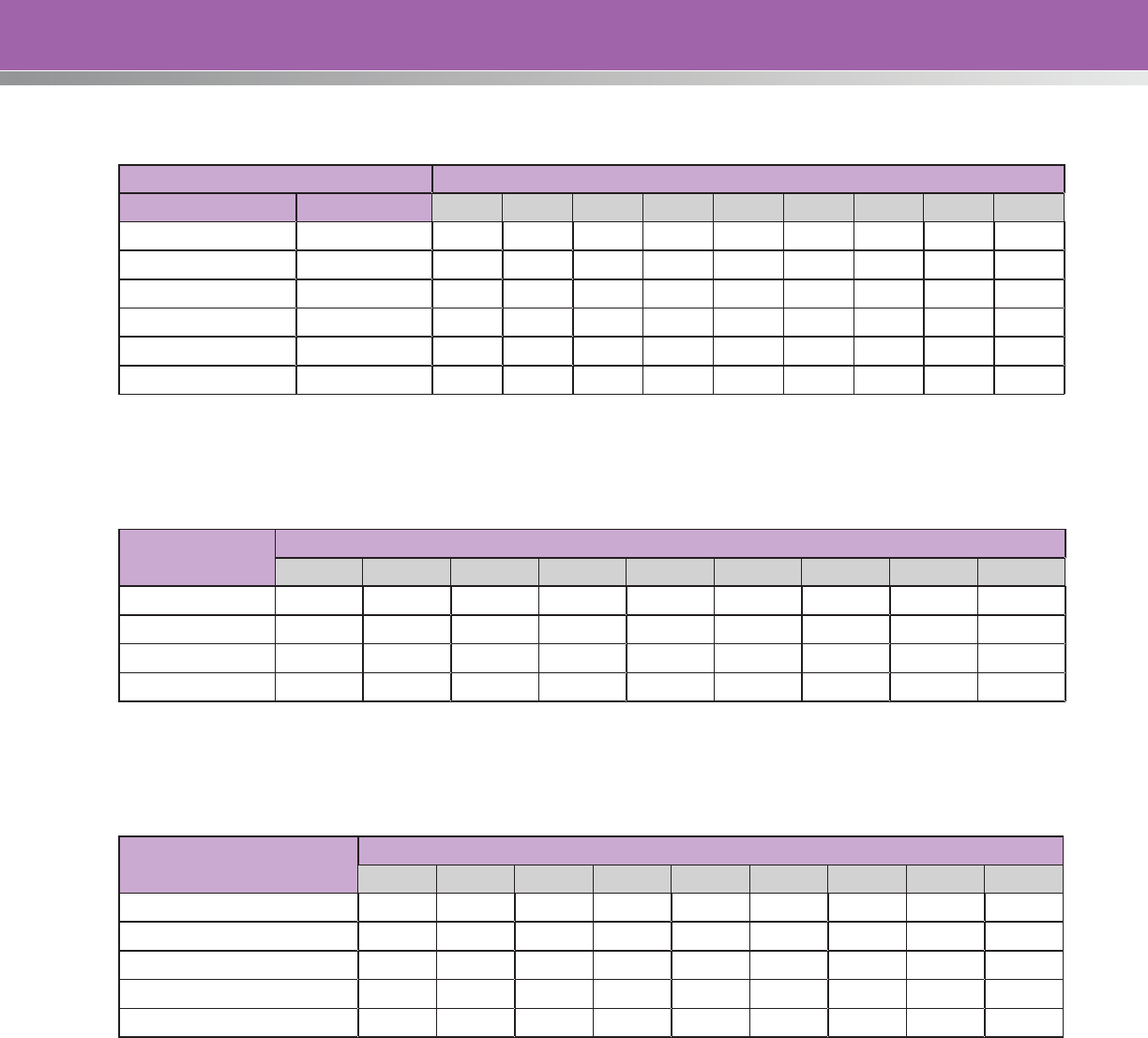
87
Table 20. Adjustment Factors for Access Density
No. of Driveways per kilometer Speed Limit from Minimum Study (km/h)
Non-Commercial Commercial 30 40 50 60 70 80 90 100 110
0 – 3 0 +15 +15 +15 +10 +10 +5 +5 0 0
4 – 6 0 +10 +10 +10 +5 +5 0 0 0 -5
7 – 12 1 +10 +10 +5 +5 0 0 0 -5 -5
13 – 21 2 – 3 +5 +5 0 0 0 -5 -5 -10 -10
22 – 30 4 – 5 +5 0 0 0 -5 -10 -10 -15 -15
> 30 > 5 0 0 -5 -10 -10 -15 -15 -20 -20
Table 21. Adjustment Factors for Lane Width
Lane width (m)
Speed Limit from Minimum Study (km/h)
30 40 50 60 70 80 90 100 110
< 2.8 0 0 0 -5 -5 -10 -10 -10 -15
2.8 – 3.2 +5 +5 0 0 0 -5 -5 -5 -10
3.3 – 3.5 +10 +10 +5 +5 0 0 0 0 -5
> 3.5 +15 +15 +10 +10 +5 +5 +5 0 0
Table 22. Adjustment Factors for Functional Classification
Functional Classification
(Urban Areas Only)
Speed Limit from Minimum Study (km/h)
30 40 50 60 70 80 90 100 110
Local 0 0 0 -5 -10 -10 -15 -15 -20
Collector +5 0 0 0 -5 -5 -10 -10 -15
Arterial +10 +5 +5 0 0 0 -5 -5 -10
Expressway +15 +10 +10 +5 0 0 0 0 -5
Freeway +25 +20 +15 +10 +5 +5 0 0 0
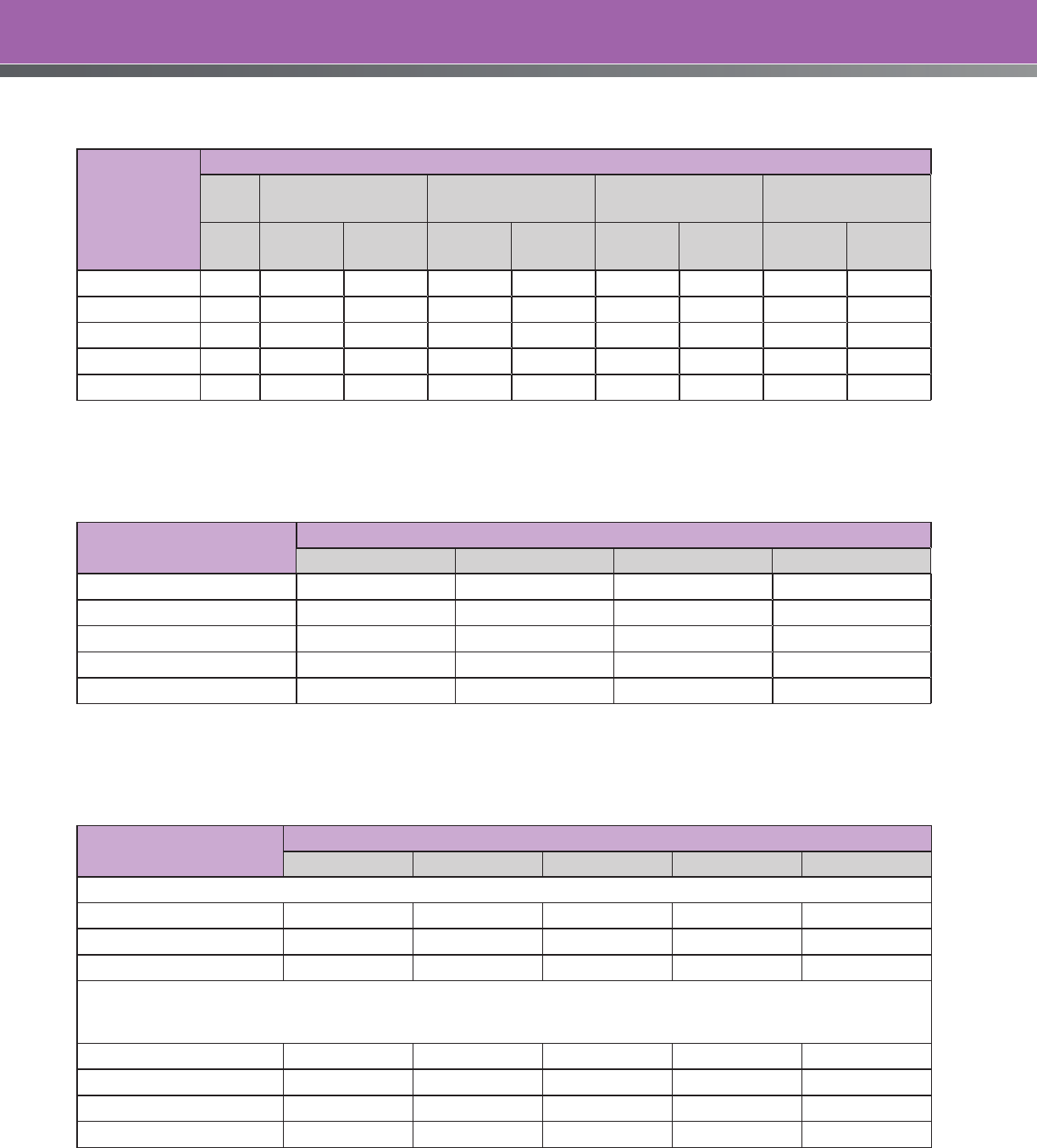
88
Table 23. Adjustment Factors for Median Type
Functional
Classification
Median
None Flush or Painted Mountable Barrier
Depressed
Unpaved
0.6m –
1.8m > 1.8m
0.6m –
1.8m > 1.8m
0.6m –
1.8m > 1.8m
1.8m –
6.0m > 6.0m
Local 0 +5 +10 — — — — — —
Collector 0 +5 +5 +10 +15 — — — —
Arterial -10 0 0 +5 +10 +15 +20 — —
Expressway — -10 -5 0 0 +5 +10 +15 +20
Freeway — — -10 -10 -5 0 0 0 0
Table 24. Adjustment Factors for Shoulder Type and Width
Functional Classification
Shoulder Type
None Turf or Gravel Stabilized Paved
Local 0 +5 +10 +20
Collector 0 0 +5 +10
Arterial -5 0 0 +5
Expressway -10 -5 0 0
Freeway -20 -10 -5 0
Table 25. Adjustment Factors for Pedestrian Activity
Pedestrian Activity
Sidewalk Setback from Edge of Pavement (m)
None 0 – 0.5 0.6 – 2.5 2.6 – 4.5 > 4.5
Age < 12
Heavy -25 -20 -15 -10 -5
Medium -20 -15 -10 -5 0
Light -15 -10 -5 0 0
If none, consider ages over 12
Age > 12
Heavy -10 -5 0 0 0
Medium -5 0 0 0 0
Light -5 0 0 0 0
None 0 0 0 0 0
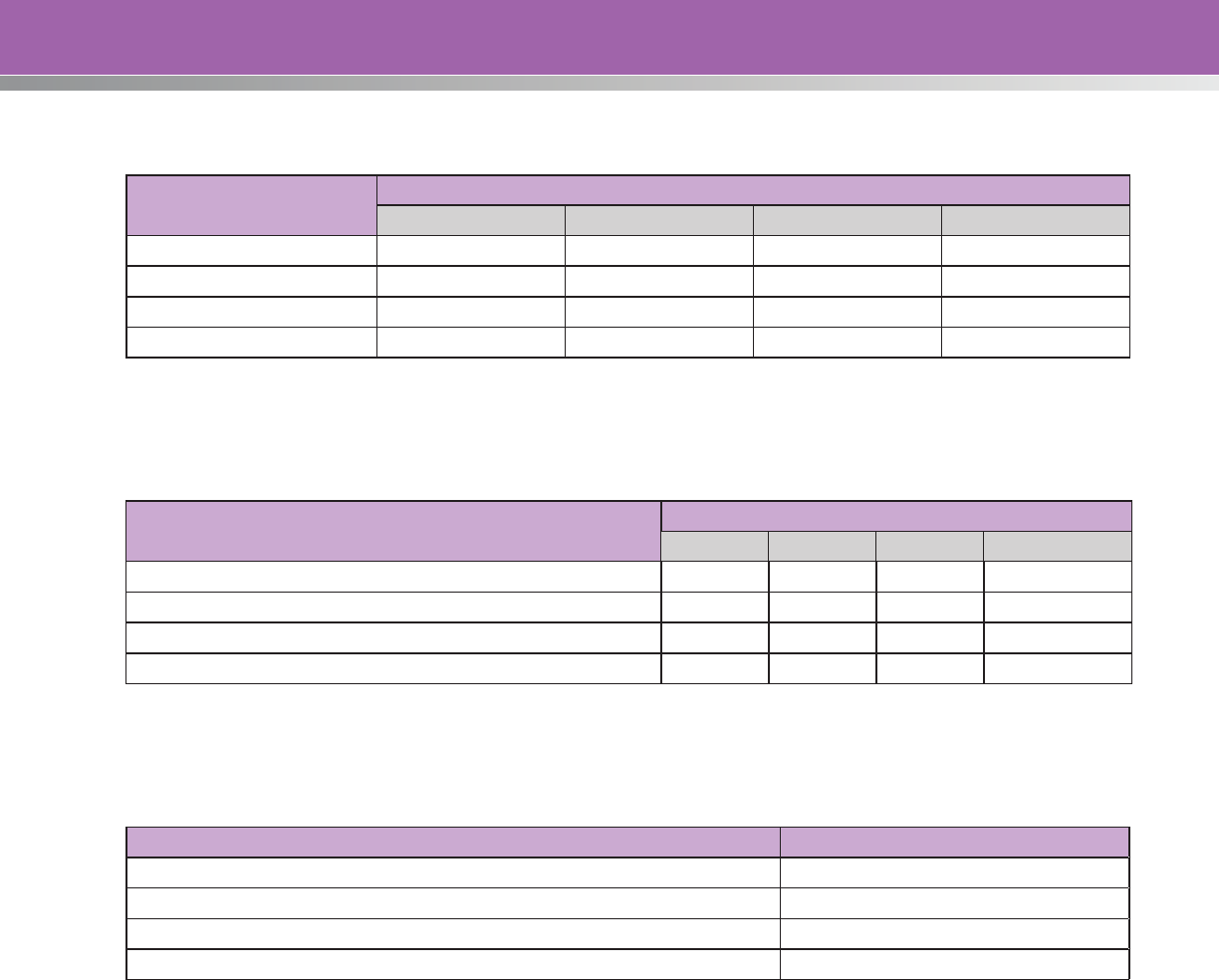
89
Table 26. Adjustment Factors for Parking Activity
Functional Classification
Parking Activity
No Parking Low Turnover Medium Turnover High Turnover
Local +10 0 -10 -10
Collector +10 0 -10 -15
Arterial +15 0 -10 -15
Expressway 0 -10 -15 -20
Table 27. Adjustment Factors for Roadway Alignment
Number of Curves per Kilometer with Advisory Speed
< Speed Limit from Minimum Study
Vertical Alignment
Level Rolling Hilly Mountainous
0 +10 +5 0 0
1 0 0 -5 -5
2 -10 -10 -10 -10
> 2 -20 -20 -20 -20
Table 28. Adjustment Factors for Crash Rate
Crash Rate as a Percent of Area-wide Rate for Similar Facilities Adjustment
< 75% +10
76% – 125% 0
126% – 200% -10
> 200% -20
Example Calculation
The following is an example calculation using the Northwestern Speed Zoning Technique:
Input Data: 85th Percentile Speed = 66.4 km/h
The 15 km/h pace = 45 to 60 km/h
Average test run speed = 56 km/h
Design Speed = 100 km/h
Average Intersection Spacing: 200 meters
Length of Proposed Speed Zone = 0.6 kms
90
For the minimum speed study, the speed measurements yield the following:
Criteria Justified Speed Limit (from Table 18) Weight Weighted Limit
85th Percentile Speed 70 3 210
Upper Limit of the Pace 60 3 180
Average Test Run Speed 60 4 240
Sum 630
The weighted average is 630/10 = 63 km/h, which suggests a speed limit of 60 km/h.
The suggested speed limit needs to be checked against the major physical features of the road using
Table 19.
Design Speed
(km/h)
Average Distance Between
Intersections (m)
Length of Proposed
Zone (km)
Maximum Speed Limit
(km/h)
110 400 1.5 110
100 300 1.0 100
90 250 0.8 90
90 175 0.7 80
70 125 0.6 70
70 100 0.5 60
50 75 0.4 50
50 60 0.3 40
30 45 0.2 30
All three criteria are satisfied with the 60 km/h speed limit. Therefore the minimum study recommends a
speed limit of 60 km/h.
For the detailed analysis, the following data is collected:
• Functional classification – Arterial
• Number of non-commercial driveways – 10/km
• Number of commercial driveways – 4.5/km
• Lane width – 3.65 m
• 4.3 m painted median
• No shoulders, and barrier curbs on both sides of the road
• Light pedestrian activity for age < 12

91
• A sidewalk with a 0.3 meter setback
• No parking allowed
• Rolling terrain
• Crash rate = 7.4 crashes per million-vehicle-kilometers (average is 5.1 crashes per million-vehicle-
kilometers for arterial roads)
The factors determined from the various tables are:
Adjustment Factors
Non-commercial Access (Table 20) +5
Commercial Access (Table 20) 0
Lane Width (Table 21) +10
Functional Classification (Table 22) 0
Median Type (Table 23) 0
Shoulder Type and Width (Table 24) -5
Pedestrian Activity (Table 25) -10
Parking Activity (Table 26) +15
Roadway Alignment (Table 27) +5
Crash Rate (Table 28) -10
Totals +35 -25 =+10
The overall adjustment factor (OAF) is +10, which can be used to determine the multiplication factor as:
MF = (100+OAF)/100 = (100+10)/100 = 1.10
The multiplication factor is less than 1.25 and greater than 0.75, therefore the recommended speed limit
is the speed limit from the minimum study multiplied by the multiplication factor and rounded to the
nearest 10 km/h:
SL = 60 km/h * 1.10 = 66 km/h ➔ 70 km/h

92
APPENDIX E: SPEED LIMITS NEW ZEALAND (ROAD RISK METHODOLOGY)
The speed limit policy in New Zealand is a national policy that aims to balance mobility and safety by
setting speed limits that are safe, appropriate, and credible for the level of roadside development and
the category of road.
The information required to determine the speed limit for a particular road is:
The existing speed limit;
• The character of the surrounding land environment (e.g., rural, fringe of city, fully developed);
• The function of a road (i.e., arterial, collector or local);
• Detailed roadside development data (e.g., number of houses, shops, schools, etc.);
• The number and nature of side roads;
• Carriageway characteristics (e.g., median divided, lane width and number of lanes, road
geometry, street lighting, footpaths, cycle lanes, parking, setback of fence line from carriageway);
• Vehicle, cycle and pedestrian activity;
• Crash data; and
• Speed survey data.
Calculating a speed limit using Speed Limits New Zealand (SLNZ) methods requires road and roadside
data collection, and the application of the set procedures specified in the policy.
Once a section of road has been identified for analysis, data collection should be commenced.
The survey should extend at least 200 meters in each direction beyond the section of road under
consideration. This is to ensure the appropriate boundary point between speed limits is identified and
features that may influence sign location are included.
Step 1: Determine Development Rating
Different types of development are allocated for the rating values as shown in Table SLNZ4. The ratings
are based on the expected number of vehicle, pedestrian and cycle movements generated each day.
For example, a house is allocated one rating unit and a large shop is given four rating units.
Development ratings are allocated for the road being surveyed (frontage development) and for
the first 500 meters of side roads (side road development). For each 100-meter section of road, the
development rating subtotal is the sum of the frontage and the side road development ratings. The
total development rating is calculated by adding the 100-meter subtotals for the length of road being
assessed for a speed limit.

93
Table E1. Development Rating
Development Type Frontage Development Rating Units
A Property or access point* with 1 or 2 dwellings**; church;
small hall; playground; beach; sports ground; camping
ground; holiday cabins; cycle path or pedestrian way
that intersects with the roadway.
1
B Property or access point* with 3 or 4 dwellings**;
business or office with fewer than ten employees; small
shop; large hall; cinema; small public swimming pool.
2
C Property or access point* with 5 or more dwellings**;
business or office with 10 to 30 employees; general
store; takeaway shop; bank; service station; cinema
complex; hotel; restaurant; large swimming pool.
3
D Business or office with more than 30 employees;
large shop; post office; hospital; tertiary education
establishment.
4
E Access point* serving two or more developments. 1 to 4***
F Primary school or kindergarten. 1 for every 15 students
G Secondary school. 1 for every 30 students
* An access point includes a private driveway and a public entrance or exit.
** A dwelling includes a house, a home unit in a block, a semi-detached home unit, and a motel unit. Each unit in a block of units
counts as one dwelling.
*** When two or more developments other than dwellings, or if dwellings and other developments share a common access point
or service road, the correct rating is the greatest of:
• the rating for a development type A, B, or C according to the number of dwellings served by the access point; or
• the highest rating for any one development, other than dwellings, served by the access point; or
• the rating determined by treating the access point as a side road and allocating the rating specied in Table SLNZ5.
Multiple access points are handled in the following manner:
• Where a single development or a small group of developments has more than one access
point on the same road, the development should be rated once only and additional access
points ignored. Developments with separate entrance and exit points should also be treated as
having only one access point. Examples include service stations, motels, schools, and a small
group of shops with off-street parking.
• Where a large group of developments, such as a shopping mall or a service road, share
more than one access point, a rating is assigned to each access point. In these situations, a
proportional number of the developments should be allocated to each access point, and each
one rated as a Development Type E.
• Separate ratings may be assigned to each access point when there are at least four individual
developments or one type D development for each access point. These conditions ensure that
94
the sum of the access point ratings does not exceed the sum of the ratings for the individual
developments in the group.
Step 2: Determine side road development rating
The side road development rating is calculated on the first 500 meters of a side road by applying the
rating values outlined in Table E1 to the development and then entering Table E2 to determine the side
road rating.
A notable difference in this step is that each school or kindergarten fronting on a side road is calculated
(differently) as follows:
• Use half the normal frontage rating (from Table E1) if a school or kindergarten is within 500 meters
from the road being surveyed; and
• Use a quarter of the frontage rating (from Table E1) if a school or kindergarten is between 500 and
1000 meters from the road being surveyed.
Note that a cross intersection is treated as two side roads.
Table E2. Side Road Development Rating
Traffic Volume on Side road
(Vehicles per Day)
Side Road Development Rating Units According to the Frontage
Development Rating (R) on the First 500 m of the Side Road
R < 8 8 < R < 20 R > 20
< 4000 1 2 3
> 4000 2 3 4
Step 3: Roadway Rating
The roadway rating is calculated by summing the ratings related to roadway activities and traffic
control. Tables E3 to E8 show the ratings that apply according to the nature and use of the road. Note
that where usage or provision of facilities is different on each side of the road, the rating is the average
of the ratings for each side.
Roadway ratings are calculated for each 100-meter section of road and the sub-total is the sum of
the ratings for each roadway activity per 100-meter section. The total roadway rating is calculated by
adding the 100-meter sub-totals for the length of road being assessed for a speed limit.
Step 4: Calculate the Rating
The average rating is calculated by summing the total development and roadway rating for the length
of road being assessed and then dividing by the number of 100-meter sections of road. However,

95
the total roadway rating must not exceed the total development rating for the length of road being
assessed. If the total roadway rating is higher, it must be reduced to that of the development rating.
Table E3. Pedestrians
Pedestrian Facilities
Pedestrian Volume (Pedestrians per Day)
< 200 > 200
Sidewalks behind boulevards or no
pedestrian access
0 0
Sidewalks adjacent to the roadway 0 1
No sidewalk but useable shoulder 1 2
Pedestrians must walk on road 1 3
Table E4. Cyclists
Cycling Facilities
Cyclist Volume (Pedestrians per Day)
< 200 > 200
Bicycle path separated by a boulevard or
fence or no cyclist access
0 0
Wide road, cyclists clear of moving traffic 0 1
Narrow road, cyclists impede moving traffic 1 2
Table E5. Parking
Parking Facilities
Normally Two Parked
Vehicles or Fewer per
100 Meters
Frequent Parking
on Both Sides, Long
Duration
Frequent Parking
on Both Sides, Short
Duration
Vehicles can park 2
meters from moving
traffic
0 0 1
Vehicles park close to
moving traffic but do
not obstruct it
1 2 3
Parked vehicles obstruct
moving traffic, i.e.,
remaining traffic lane is
3 meters or less
2 3 4
96
Table E6. Road Geometry
Type of Roadway
Alignment
Open Visibility Average Visibility Limited Visibility
One-way traffic or divided roadway
(solid median or barrier)
0 0 0
4 or more lanes (flush median or
undivided)
0 1 1
2 or 3 lanes (flush median or undivided) 0 1 2
1 lane (two-way) 3 4 5
Table E7. Traffic Control
Traffic control (applying to traffic on the road surveyed) Rating Unit
Pedestrian crossing 3
“Stop” control 3
YIELD Sign 2
Traffic signals 2
Railway level crossing 1
Traffic islands 1
Table E8. Development
Type of Development
Status of Road
Local Road Collector Road Arterial Road
Residential 2 1 0
Industrial 1 0 0
Commercial 0 0 0
Rural Residential 1 0 0
Rural 0 0 0
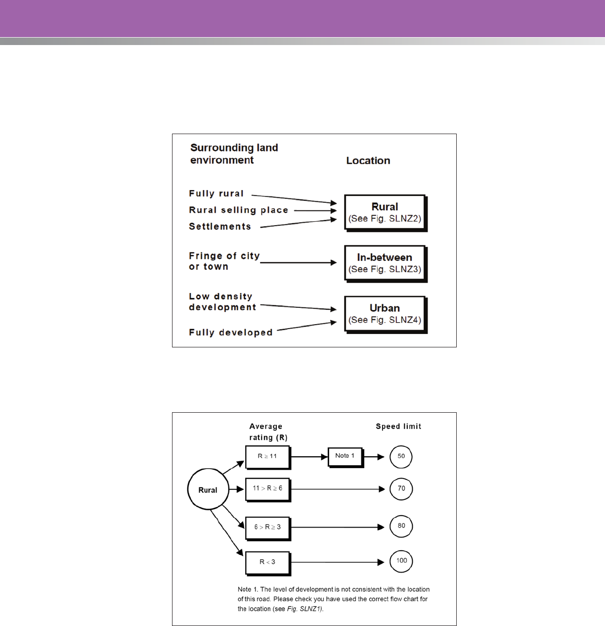
97
Step 5: Determine the Speed Limit
When the average rating has been calculated, the speed limit is determined as follows.
Figure SLNZ1. Determining Speed Limit.
Figure SLNZ2. Speed Limit Flow Chart—Rural.
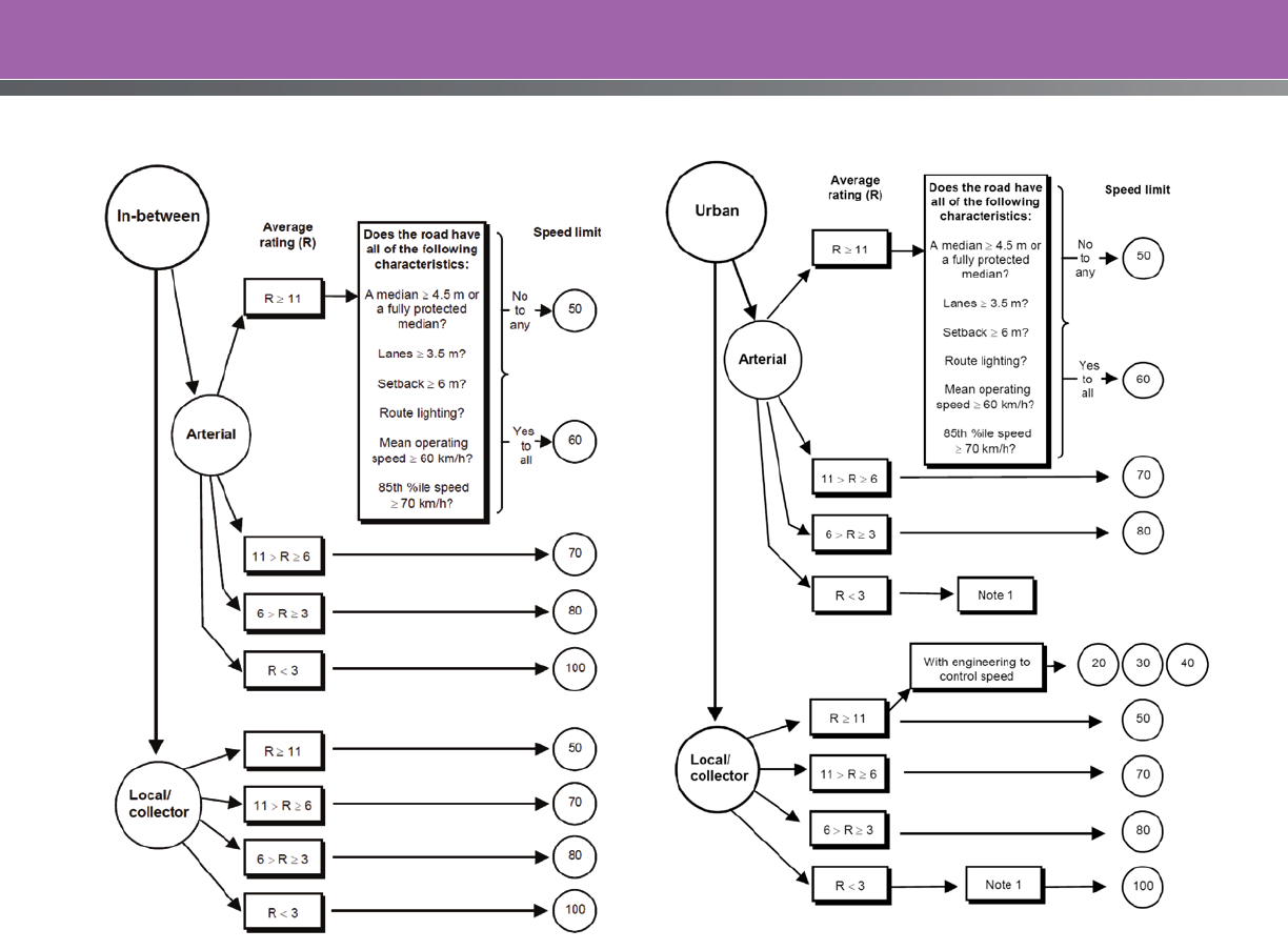
98
In rare instances, because of special features or activities along a road, SLNZ cannot be used or will
not produce a sound result. SLNZ must always be used with reference to speed limits policy, and in
conjunction with sound engineering judgment, to determine the appropriate and safe speed limit.
Figure SLNZ3. Speed Limit Flow Chart—In-Between. Figure SLNZ4. Speed Limit Flow Chart—Urban.
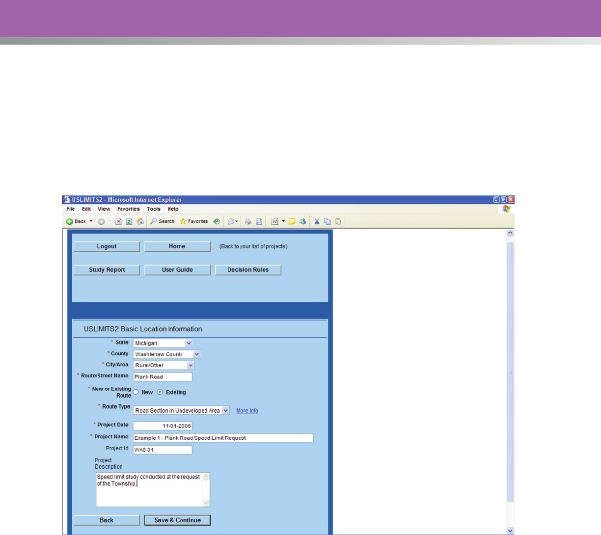
99
APPENDIX F: EXAMPLE CASE STUDY USING USLIMITS2
Example 1: Speed Limit Request on a Two-Lane Road in an Undeveloped Area
The first example is a two-lane road in a rural area. At the request of the Township officials, the engineer
has been asked to conduct a traffic and engineering investigation to determine if the existing maximum
50 mile-per-hour speed limit should be lowered. Based on data collected during the investigation, the
USLIMITS2 screens below show the input variables and final suggested speed limit for this road section.
This is the Basic Location Information input screen:
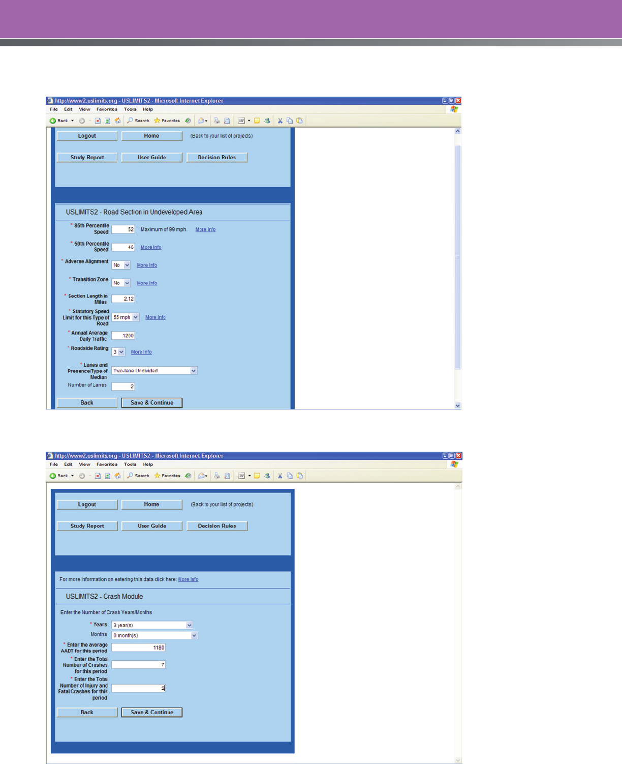
100
This is the basic input screen for the 85th percentile speed and other variables:
This is the input screen for the crash data:
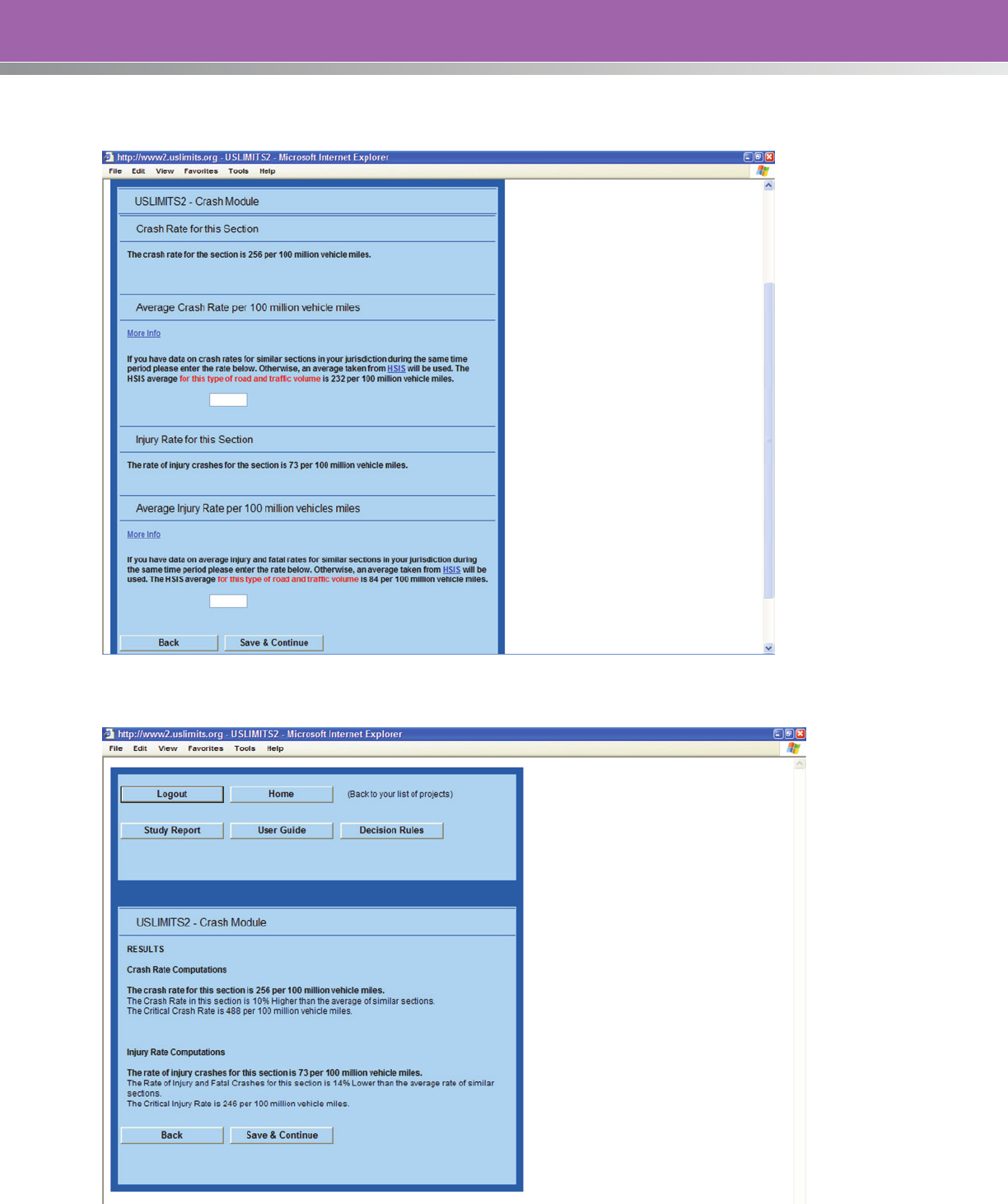
101
This is the crash summary generated by USLIMITS2 based on the crash data input by the user:
This screen provides a summary of the crash calculations:
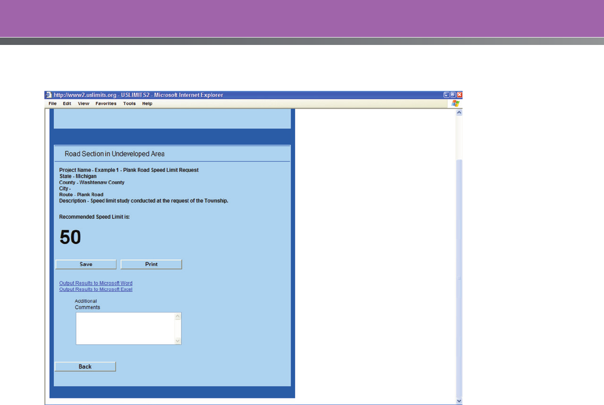
102
This is the final output screen showing the advisory recommended speed limit for this rural road section:

103
The results can also be printed to a Microsoft Word file as shown below:
USLIMITS2 Data Output
Top of Form
Basic Project Information
Project Name – Example 1 – Plank Road Speed Limit Request
Project Number – WAS 01
Project Date – 11-01-2006
State – Michigan
County – Washtenaw County
City –
Route – Plank Road
Route Type – Road Section in Undeveloped Area
Route Status – EXISTING
Roadway Information
85th Percentile Speed – 52 mph
50th Percentile Speed – 46 mph
Section Length – 2.12 mile(s)
Statutory Speed Limit – 55 mile(s)
AADT – 1200
Adverse Alignment – No
Lanes and Presence/Type of Median – Two-lane road or undivided multi-lane
Number of Lanes – 2
Roadside Hazard Rating – 3
Crash Data Information
Crash Data Months/Years – 3.00
Crash AADT – 1180
Total Number of Crashes – 7
Total Number of Injury Crashes – 2
Section Crash Rate – 256
Section Injury Rate – 73
Crash Rate Average for Similar Sections – 232
Injury Rate Average for Similar Sections – 84
Comments –
Recommended Speed Limit is: 50
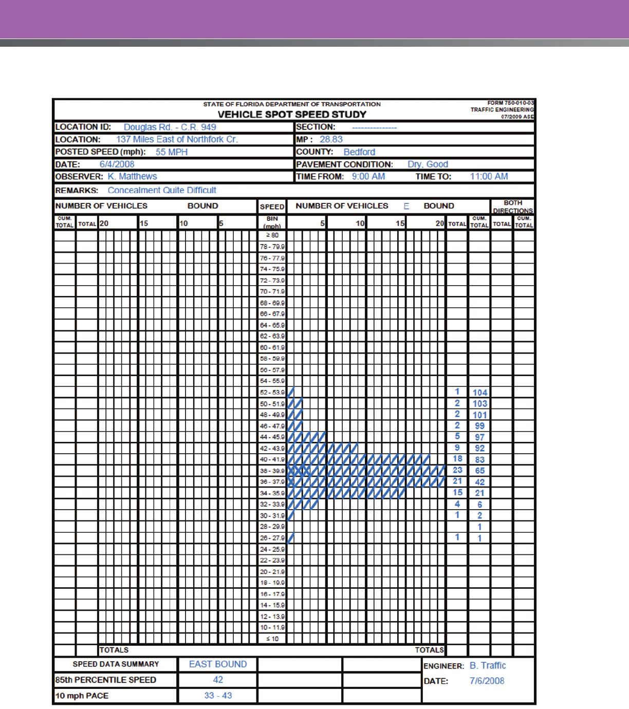
104
APPENDIX G: EXAMPLE SPEED STUDY FORMS
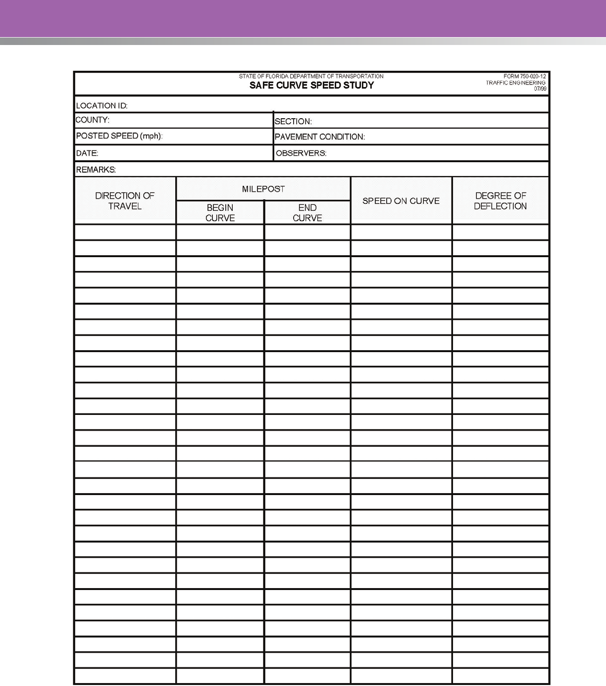
105
106
APPENDIX H: SAMPLE 85th PERCENTILE SPEED CALCULATION
The 85th percentile is the speed at which 85 percent of the observed vehicles are traveling at or below.
This percentile is used in evaluating and recommending posted speed limits. Weather conditions may
affect speed percentiles. For example, observed speeds may be slower in rainy or snowy conditions.
A frequency distribution table is a convenient way to determine speed percentiles. An example, from
Iowa, is given in Table 29. The frequency of vehicles is the number of vehicles recorded at each speed.
The cumulative frequency is the total of each of the numbers (frequencies) added together row by row
from lower to higher speed. The fourth column is a running percentage of the cumulative frequency.
Table 29. Example Frequency Distribution Table
Speed (mph)
Frequency of
Vehicles
Cumulative
Frequency
Cumulative
Percent Speed Percentile
15 1 1 1%
18 2 3 3%
21 6 9 9%
24 12 21 21%
27 13 34 34%
30 20 54 54%
33 18 72 72%
85th
36 14 86 86%
39 6 92 92%
42 6 98 98%
45 1 99 99%
48 1 100 100%
Source: Handbook of Simplified Practice for Traffic Studies, Center for Transportation Research and
Education, Iowa State University.
The 85th percentile speed is determined from the cumulative percent column. For the example data in
Table 4, the 85th percentile falls between 33 and 36 mph. The calculation of speed percentiles is easier
if a sample size of 100 vehicles is collected. When the sample size equals 100 vehicles, the cumulative
frequency and cumulative percent are the same.
As can be observed from Table 29, the exact 85 percent (85th percentile) is not found in the cumulative
percent column. To reach these exact percentages, a calculation is completed using percentages and
speeds from the distribution table. Shown below is the equation for calculating speed percentiles:
()
min
S
min
S
max
S
PP
PP
D
S
minmax
minD
+−
−
−
=
where SD = speed at P
D
, P
D
= percentile desired, P
max
= higher cumulative percent, P
min
= lower
cumulative percent, S
max
= higher speed, and S
min
= lower speed.

107
The 85th percentile of speed (P
D
= 85 percent) falls between 33 and 36 mph (see Table 29), so S
max
=
36 mph and S
min
= 33 mph. The higher cumulative percent (P
max
) is 86 percent, and the lower cumulative
percent (P
min
) is 72 percent. To find S
D
at P
D
in this case (85th percentile of speed),
()
mph mph mph mph
D
S 8.35333336
%72%86
%72%85
=+−
−
−
=
On highways carrying low traffic volumes, the checks at any one station may be discontinued after 2
hours, although a minimum of 100 vehicles have not been timed.
The above procedure is generally automated in commercially available computer spreadsheets or
workbooks. For example, Microsoft Excel has a PERCENTILE function that can be used to determine the
50th, 85th or any other percentile from an array of numbers.

For More Information:
Visit http://safety.fhwa.dot.gov
FHWA, Office of Safety
Guan Xu
202-366-5892
FHWA-SA-12-004
